A tantalum polymer capacitor is constructed with a tantalum (Ta) anode, a tantalum pentoxide (Ta2O5) dielectric, and a solid polymer electrolyte. This construction method offers a variety of advantages, including high-temperature ratings and stability over temperature, voltage, and time. These characteristics allow tantalum polymer capacitors to meet and exceed AEC-Q200 automotive standard requirements. KEMET tantalum polymer capacitors (KO-CAPTM series) offer low ESR to minimize power losses and unwanted noise and can withstand high temperatures and extended lifetimes of automotive applications. Specifically, the T598 tantalum polymer capacitor has ideal high capacitance, low ESR, and exceptional ripple performance, supporting increased power consumption on AD and ADAS DCUs.
Autonomous Driving is a highly complex system that consists of many different tasks. To support the highest level of autonomy, the EE architecture evolution is moving from a large number of ECUs to functional DCUs, such as AD/ADAS, Connectivity, Smart Cockpit, etc., to ZCUs with centralized computer and zonal gateways.
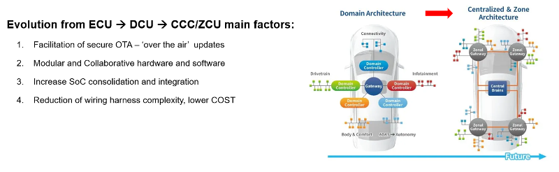
Figure 1 – EE Architecture Evolution ECU -> DCU -> ZCU/CCU and Key Change Factors
In recent years, autonomous electrical vehicle development has gained significant attention from researchers and engineers.(1) Many changes are revolutionizing the automotive EE architecture, leading to autonomous driving and the associated challenges. An autonomous vehicle must be capable of sensing the environment and safely navigating without human input.(2) The US NHTSA has defined 5 different levels of autonomy. (3)
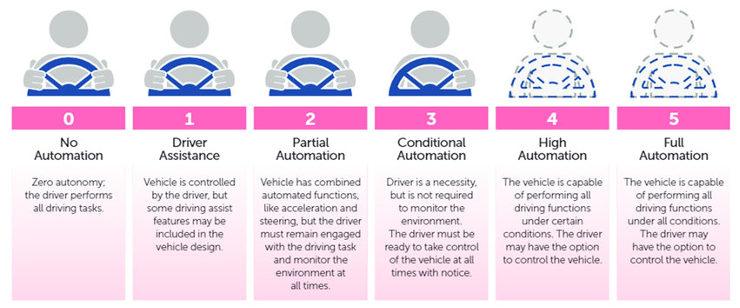
Figure 2 – Levels of Autonomous Driving by NHTSA (US Department of Transportation’s National Highway Traffic Safety Administration)
On the higher autonomy levels, the vehicles must sense their surroundings using multiple sensors, such as LiDAR, Cameras, GPS, etc. Based on the sensor inputs, the vehicles need to locate themselves and, in real-time, make decisions and act on driving. The abbreviation ADAS stands for advanced driver-assistance systems. The sensors aim to improve driving safety and are called Sensing. On the other hand, the abbreviation AD refers to autonomous driving, in which the AD system processes the data from sensing, making decisions, and command orders to actuators (brake, steering, etc.). It is named Cognitive ('brain' with the ability to process sensing data, perception, and decision), as presented in Figures 3 and 4. The KEMET T598 Automotive Polymer Grade Series has been successfully on the different functional DCUs.
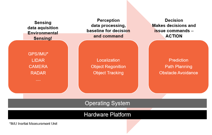
Figure 3 – Tasks in Autonomous Driving: 3 main stages: Sensing -> Perception and Decision
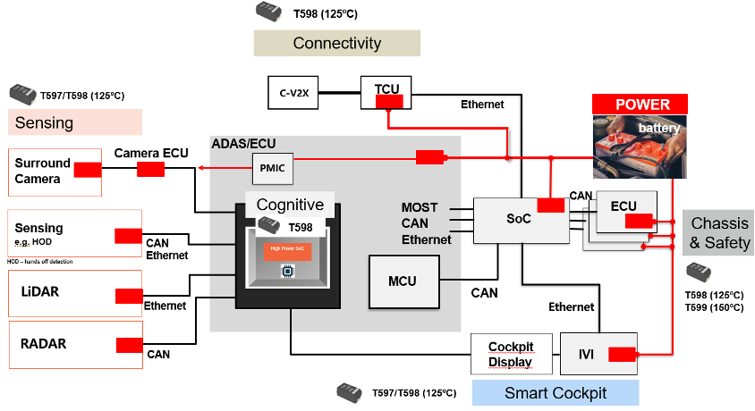
Figure 4 – Automotive Placement Strategy with Polymer Capacitors
AD computing systems can be divided into computation, communication, storage, security/privacy, and power management. (4)
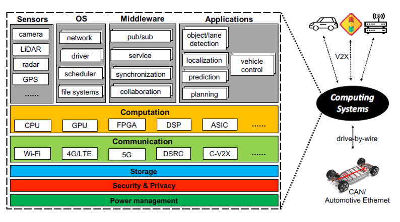
Figure 5 – Schematic EE AD Computing System
The continuous effort to increase the autonomy level significantly enhances computing system capabilities for AD. According to Liangkai et al. (4), today's “state-of-the-art” computing system for AD includes 7 performance metrics, 9 key technologies, and 11 open challenges.
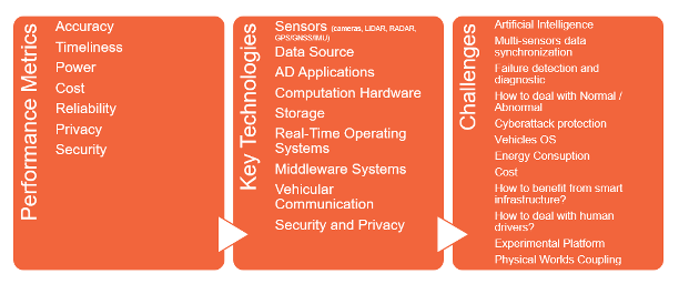
Figure 6 – AD Computing Systems State of the Art and Challenges
As the level of autonomous driving increases, the number of sensors installed must increase accordingly to acquire data on the surrounding environment. As the number of sensors increases, the amount of data processed by SoC increases, and the power consumption of the main semiconductor device that performs data processing increases. This evolution increases power consumption and optimizes the cognitive 'brain' capabilities.
Inside a DCU schematic exists (a) a transceiver circuit that communicates with sensing ECUs, (b) an SoC (System on a Chip) that processes data and makes decisions, (c) various memories (DDR/Flash), (d) a microcontroller MCU that controls driving based on the information assessed by the SoC, and (e) DC/DC converter power supply circuits to operate the various functions with different voltage rails (<1V, 3.3V, 5V etc.), shown in Figures 7 and 8
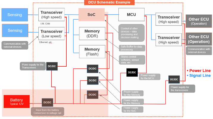
Figure 7: Schematic example - AD/ADAS DCU, highlight in light orange the DC/DC sequence from battery to SoC
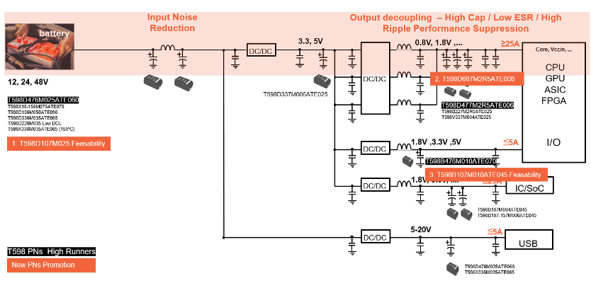
Figure 8: Schematic example - AD/ADAS DCU, highlight in light orange the DC/DC sequence from the battery to SoC processing the Sensing collecting data.
The SoC power line, typically with a voltage lower than 1V and current > 25A, on the DCUs/ZCU/CCUs requires components capable of: "high current," "low loss," "miniaturization," "high-frequency operation," and "high accuracy (voltage)." T598 capacitors with volumetric efficiency and 2.5V-rated voltage high capacitance offerings are suitable options. Typically, rated capacitance between 220 to 680uF and single-digit ESR solutions are preferred.
It is common for DC/DC converters to use T598 polymer capacitors for noise reduction at the input and smoothing/decoupling at the output, typically the T598D476M025ATE060 (EIA 7343-31 47uF25V, 60mOhm) has been adopted at the input and the T598D477M2R5ATE006 (EIA 7343-31 470uF2,5V, 6mOhm) has been successfully designed at output smoothing/decoupling. To further advance future needs, KEMET now has prototype samples available for the next generation of input noise reduction, with the T598D107M025ATE050 (EIA 7343-31 100uF25V, 50mOhm) and capacitance extension T598D687M2R5ATE006 (EIA 7343-31 680uF2,5V, 6mOhm) for optimum output smoothing.
The demand increase in power consumption to support higher processing data and action will continue to use the T598 Series' main advantages: high capacitance combined with low capacitance roll-off in frequency and temperature stability, low ESR and high ripple performance, and extended life span performance.
The T598 Series with the specific case size EIA 7343-31 with 470uF rated capacitance and 2.5V rated voltage and single digit ESR (6mOhm at 100kHz/Room temperature) has been successfully adopted in ADAS /AD DCUs.
(a) Design, Material Settings, and Process – Capacitor Reliability
The design, material settings, and manufacturing process lead to robust performance and high reliability. The over-formation during the Ta2O5 dielectric build-up allows a significantly high breakdown voltage (~14V), figure 9.
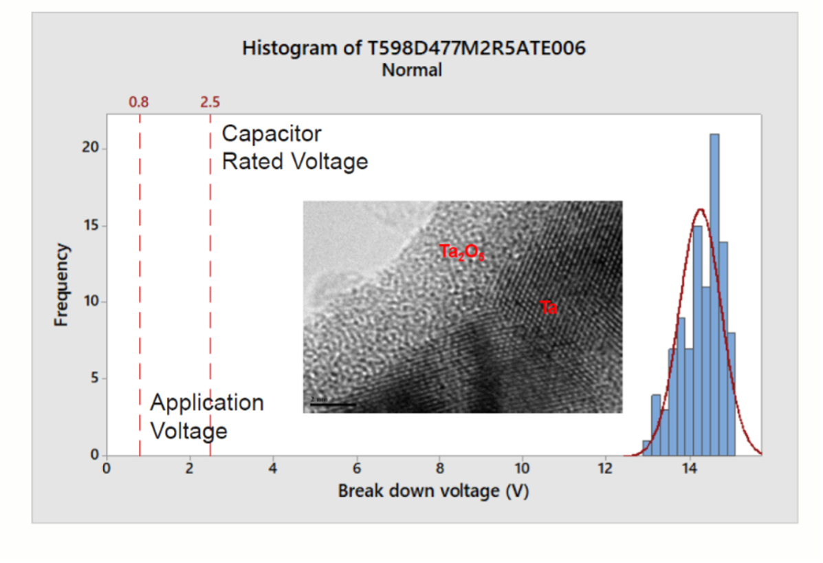
Figure 9. T598D477M2R5ATE006 470uF 2.5V 6mOhm Break Down Voltage (V) Histogram
(b) Surge Current Performance
Combined with the robust reliability design, the capacitors are 100% inline subject to surge current screening at rated voltage, 4 cycles, and room temperature with a circuit resistance of < 0.5 ohms. To evaluate the extended performance, extra surge current tests were performed at room temperature, 2.5V, with <0.1 ohm low resistance showing a maximum peak of 16.6A, Figure 10. All the electrical parameters were inside the initial specification after testing.
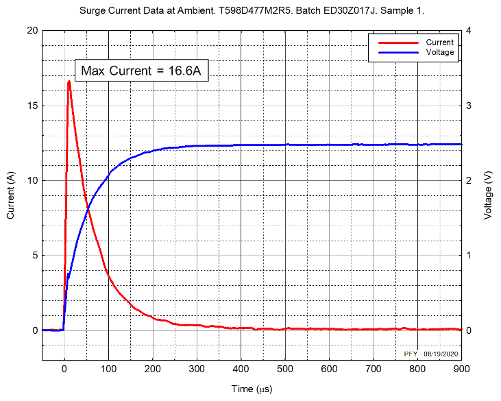
Figure 10. T598D477M2R5ATE006 Low Resistance Surge Current Results
(c) Ripple Current Performance
Another important topic is the T598D477M2R5ATE006 ripple current specification, defined in the table below. This advanced ripple capability is a key factor for optimum operation.
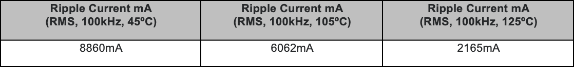
The ripple noise included in the output voltage of DC/DC needs to be suppressed. An output ripple voltage of a step-down switching power supply is generated by the ripple component of the current flowing through the inductor and the capacitance, ESR, and ESL of the output capacitor. To suppress the output ripple voltage, increasing the capacitance and decreasing the output capacitor's ESR is effective.
Additionally, Load Ripple life testing at 125ºC, 1.25V up to 1,000h reveals high stability in Capacitance Loss, with the Delta Cap variation lower than 2%; the leakage current, dissipation factor, and the ESR also reveal electrical stability, shown in figure 11.
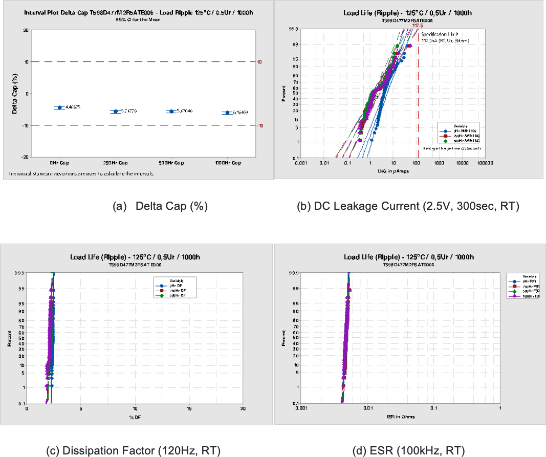
Figure 11. T598D477M2R5ATE006 Load Life Ripple Testing – 125ºC 1.25V up to 1,000h
(d) ESR versus Frequency
The ESR performance over the frequency range shows a large and broad distribution below 10mOhm for 1 single capacitor, figure 12. The combination of several capacitors in parallel reduces the ESR and supports the SoC power consumption trend on node sizes lower than 16nm.
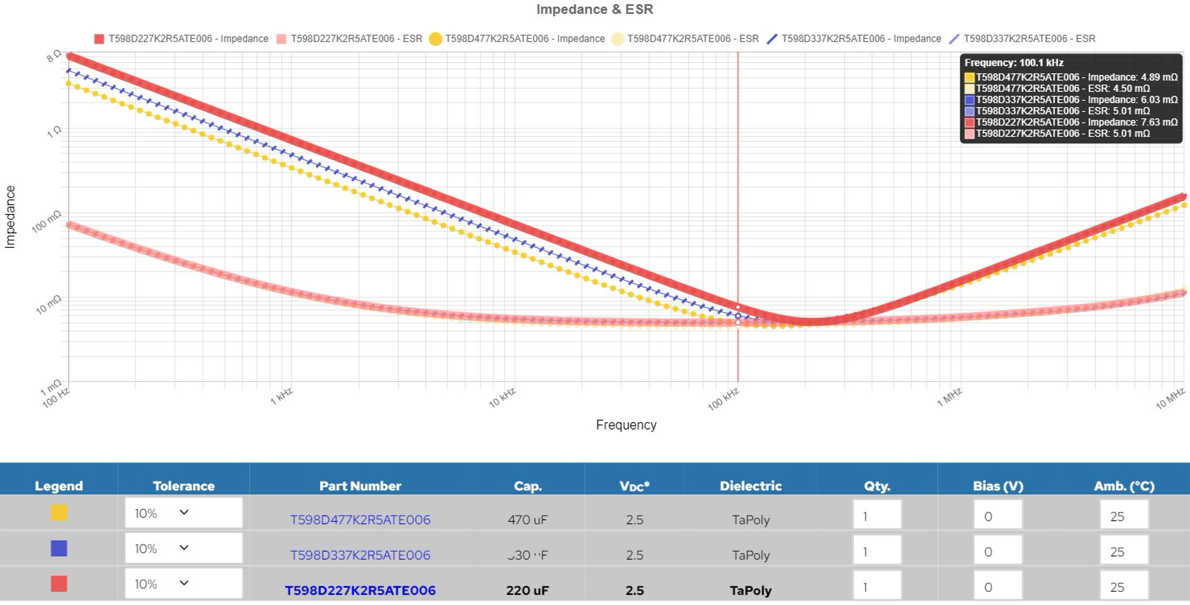
Figure 12. T598 K-SIM Graphic – Impedance and ESR 220-470uF 2.5V 6mOhm capacitors.
(e) Accelerated Storage Testing – Cap Loss and ESR Aging Modelling
During the last decade, the automotive segment extended the 'legacy' lifespan mission profile from 8,000-40,000h to ~130,000h (15 years). The T598 polymer capacitors have been extensively subject to accelerated storage tests to support the ESR Aging and Cap Loss modeling. The temperature is a key factor, and the Arrhenius formula has been followed; the experimental activation energy is Ea=1.0eV, shown in figure 13

Figure 13. T598 Cap Loss and ESR Aging Modeling
Conclusion
The T598 Polymer Automotive Grade offers solutions to designers where space board saving, high volumetric efficiency/miniaturization, and reliability are required. Please contact a sales representative to support you in your challenge designing DCU/ZCU/CCU applications.
References
(1) 'Overview analysis of recent development of Self-Driving Electrical Vehicles,' Qasim Ajao and Landre Saqeeq Georgia Southern University
(2) ‘CAAD: Computer Architecture for Autonomous Driving,' Shaoshan Liu, Jie Tang, Zhe Zhang and Jean-Luc Gaudiot, IEEE
(3) Policy of Automated Vehicles, NHTSA
(4) ‘Computing Systems for Autonomous Driving: State-of-the-art and Challenges,' Liangkai Liu et al.
T598 Series