EV Pump and KEMET METCOM Inductors
Key Resources
KEMET METCOM inductors can be used in pump applications for automotive. This application note will review the different types of pumps and how they differ.
A pump is a machine used to suck up or send a medium (usually gas or liquid such as water or oil) by generating pressure to the medium. The pressure can be positive or negative. From an energy standpoint, pumps transfer energy (usually mechanical or electrical) into pressure applied to the medium.
Usually, the name of a pump is determined by its type of medium. The following three mediums are typically used in automotive applications:
| Medium | Pump name |
|---|---|
| Gas | Gas pump |
| Water | Water pump |
| Oil | Oil pump |
Strictly speaking, a compressor is also a type of pump because the principle is almost identical. The difference between a compressor and a pump is that a compressor exerts greater pressure on a medium to compress it, compared with a pump, which is typically used for drawing in and delivering the injected medium. In general, compressing a medium requires a higher operational power than is needed for a pump.
The term "pump" will signify pumps and compressors throughout this application note.
Automotive pumps can be classified into mechanical and electrically controlled pumps.
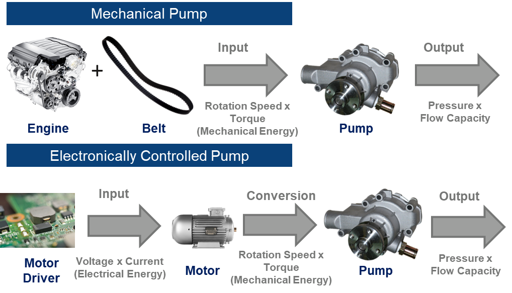
A mechanical pump refers to a pump that derives power from the engine. Generally, the engine's power is fed to a water pump through a belt system. Therefore, the pump works in conjunction with the engine. The operation speed of the pump is proportional to the engine's rotation speed. As a result, when the engine runs at high speed, the pump will also run at high speed. When the engine stops, the pump will also stop. That means a mechanical pump is a passive module, one of the main features of mechanical pumps. Figure 1 below shows some examples of a mechanical pump and its surroundings.
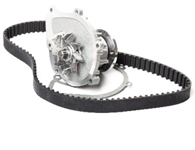
Water pump and belt
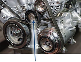
Water pump installed in a vehicle near the engine
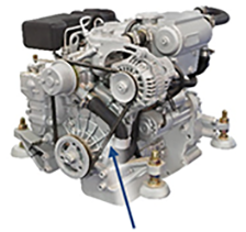
Engine and its belt system
Figure 1 – Examples of Mechanical Pumps
Unlike a mechanical pump, a motor drives an electric pump instead of an engine. It does not require a belt system to work. Therefore, it is independent of the engine's operation, and the speed is not affected by the state of the engine. So, it is an active module.
Figure 2 shows the structure of an electronically controlled pump driven by a brushless motor.
We will focus on electronically controlled pumps (E Pumps) in the rest of this article.
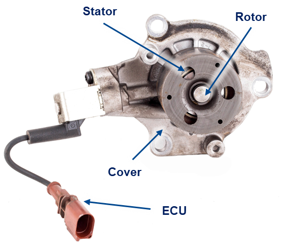
Figure 2 – Water Pump Structure with Brushless Motor
Whether it is a mechanical pump or an electronically controlled pump, the following equation will be true:
Calculating the efficiency of a pump is very complicated, as we need to consider the power loss related to pump type, motor/transmission, pump head, medium, etc. For ease of understanding, we can ignore the efficiency to see better the relationship between the input and output power of mechanical and electronically controlled pumps, as seen in Figure 3.
As seen from Figure 3, although the form of energy input between the two types is different, the final output energy from each of the pumps is the same: pressure and flow capacity.
The market has many different names for pumps based on various variables. Understanding the principle behind how pumps work can help clarify the differences between these products.
As mentioned earlier, the purpose of the pump is to apply pressure to a medium and provide flow capacity. Pumps in automotive applications can be used for the following purposes:
There are many places within the vehicle where pumps are used for these purposes, and some will be more important to the vehicle's overall operation. For example, if the fuel pump does not work, it will immediately affect the vehicle's operation, so this pump is integral to the vehicle's overall performance. Alternatively, if the wiper pump does not work, it will only cause a minor inconvenience, so its importance is much lower than the fuel pump.
With the shift from traditional gasoline vehicles to BEVs, some applications will be eliminated, while some new applications will be added. For example, fuel pumps are no longer used in BEV, but cooling water pumps for high-voltage batteries will be added. Considering a range of factors, pump usage in different applications is summarized in Table 1.
All applications will not be discussed in this article. Major applications have been selected for discussion in the following sections.
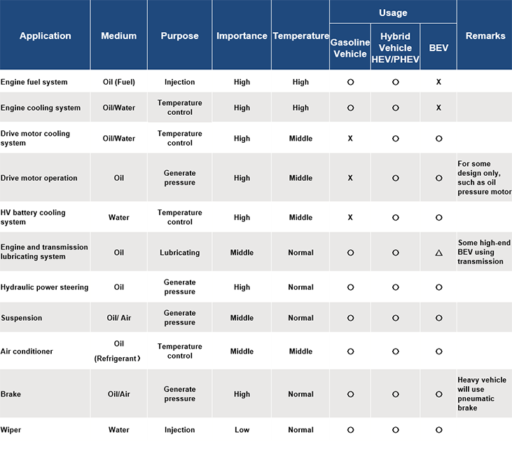
Table 1 – Overview of Automotive Pump Applications
There are a few types of fuel injection systems in the market (for example, inline injection pump fuel systems, common rail fuel injection systems, etc.) – no matter which fuel injection system, the fuel pump is a necessary component.
Figure 4 shows an example of the structure of a common rail fuel injection system, one of the central fuel systems used today. The function of the feed pump is to draw in fuel from the fuel tank and send it to the high-pressure fuel pump. The fuel is then pressurized and sent to the common rail. From there, the fuel is injected using the injection valve. An ECU controls these processes.
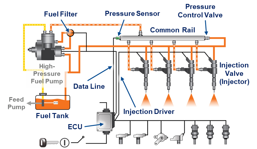
Figure 4 – PFI Engine Example
The feed pump is installed inside the fuel tank and is called an in-tank pump, whereas the high-pressure fuel pump is installed outside the fuel tank and is called an out-tank pump in this example. The in-tank pump needs to work at a higher ambient temperature. This temperature requirement is because a part of the incombustible fuel will return to the oil tank through the return pipe during engine operation, increasing the temperature of the entire fuel tank. In some countries, due to high outdoor temperatures, sometimes the temperature inside the fuel tank reaches up to 100°C.
Although the high-pressure fuel pump is outside of the fuel tank, the average temperature of the fuel can reach up to about 70°C because of its proximity to the elevated temperatures of the fuel tank. In addition, the engine will also deliver heat to it, so its operating temperature is not low. For these two pumps, some automotive manufacturers require working temperatures up to 135°C.
Figure 5 shows the position of a common rail fuel system in a vehicle.
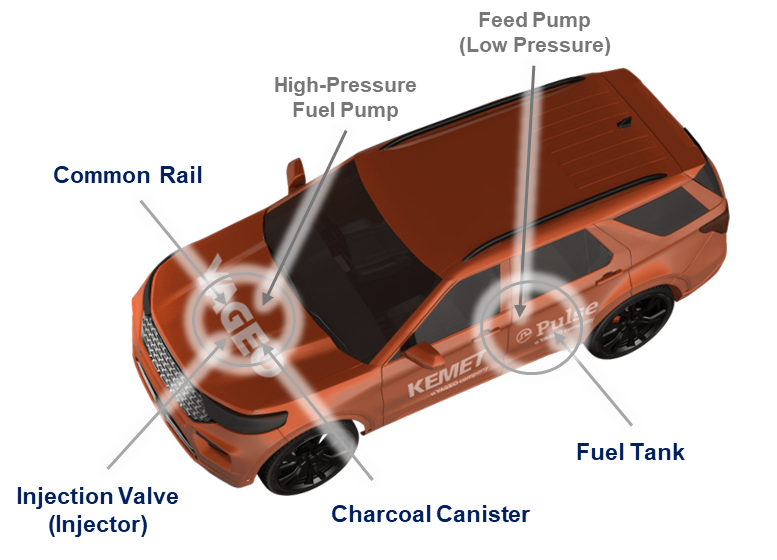
Figure 5 – Automotive Common Rail Fuel System
The direct injection fuel engine uses a high-pressure fuel pump to spray fuel directly into the combustion chamber in a high-pressure atomized state. The fuel mixes with the air in the combustion chamber and ignites. Because of disadvantages such as high costs, environmental pollution, and accumulation of waste on valves and exhaust pipes that cannot be completely burned, this engine was once almost completely replaced by the port fuel injection (PFI) engine.
However, thanks to the advancement of technology, the shortcomings of direct injection fuel engines have been alleviated. Because its working principle is particularly compatible with turbo cars, it has been recently adopted by many automotive manufacturers. Turbo applications use its advantages, such as larger torque output, fuel efficiency, and lower combustion temperature.
Figure 6 shows the structure of a direct fuel injection engine with a common rail fuel system. The positions of some of the main parts are shown in the figure.
Unlike a PFI engine, the high-pressure fuel pump must be installed close to the combustion chamber. Therefore, the high-pressure fuel pump needs to work at high temperatures.
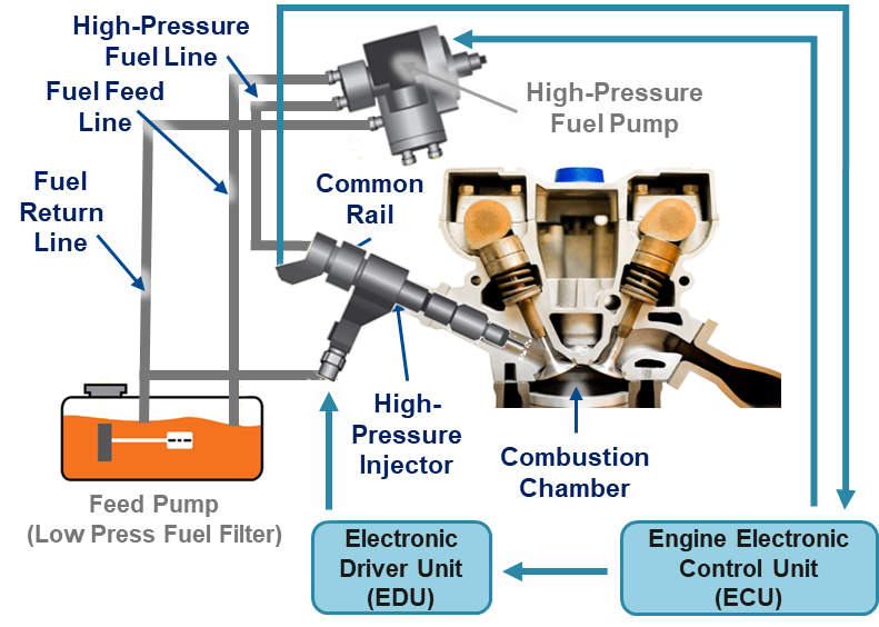
Figure 6 – DI Engine with a Common Rail Fuel System
Figure 7 is a DI engine photo that shows the position of the high-pressure fuel pump.
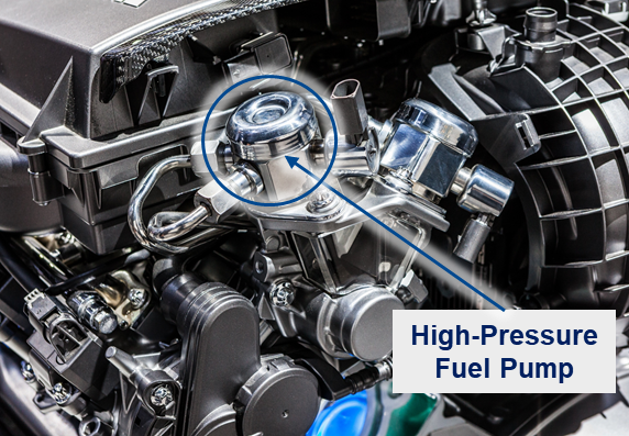
Figure 7 – High-Pressure Fuel Pump Position
Each part of the vehicle has its working temperature. A cooling system is used to maintain this temperature and is necessary for engine applications.
In the 1980s, because cooling technology at that time was not advanced, cars would often fail to run and emit smoke due to the engine overheating when climbing hills. Figure 8 shows an engine overheating due to this reason. In the worst case, this overheating would cause engine burn-in.
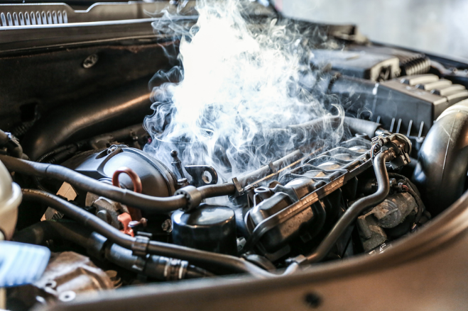
Figure 8 – Engine Overheat
There is no doubt that the cooling system is a vital part of a vehicle, but the word "cooling" is very misleading. People may think that the colder the engine, the better. However, the engine has its ideal working temperature, usually around 80°C ~90°C. If the engine is too cold, the clearance between the internal piston and cylinder will be widened, which makes the engine inefficient.
Therefore, a car has a water temperature gauge on the dashboard to show the cooling water temperature and notify the driver of any temperature issues (Figure 9). The temperature gauge ranges between values of C and H. The water temperature is 70°C or lower if the dial is on C. The engine is said to be overcooled at temperatures below 70°C. The water temperature is 100°C or higher if the dial is on H. High temperatures such as this can cause the engine to overheat. In Figure 9, the dial is in the middle of H and C, so the water temperature is about 80°C~85°C, which is within the normal, suitable range of the engine.
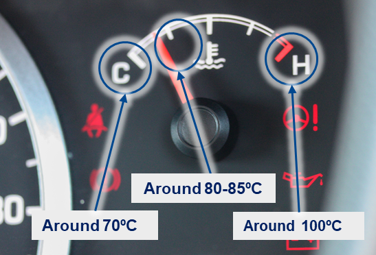
Figure 9 – Water Temperature Gauge
Figure 10 shows the structure of an engine cooling system in a vehicle. It comprises a water pump, heater, fan, thermostat, and radiator. The water pump generates pressure and provides a flow capacity to the coolant. Usually, LLC (Long Life Coolant) will be used. The coolant goes through the pipeline surrounding the engine cylinder head and block (called a water jacket) and is sent to the radiator. Then, the coolant returns to the pump again. In this cycle, the coolant absorbs the heat in the water jacket generated by the engine cylinder and brings it to the radiator, using a fan to exhaust the heat outside the vehicle. The radiator is installed at the front of the engine.
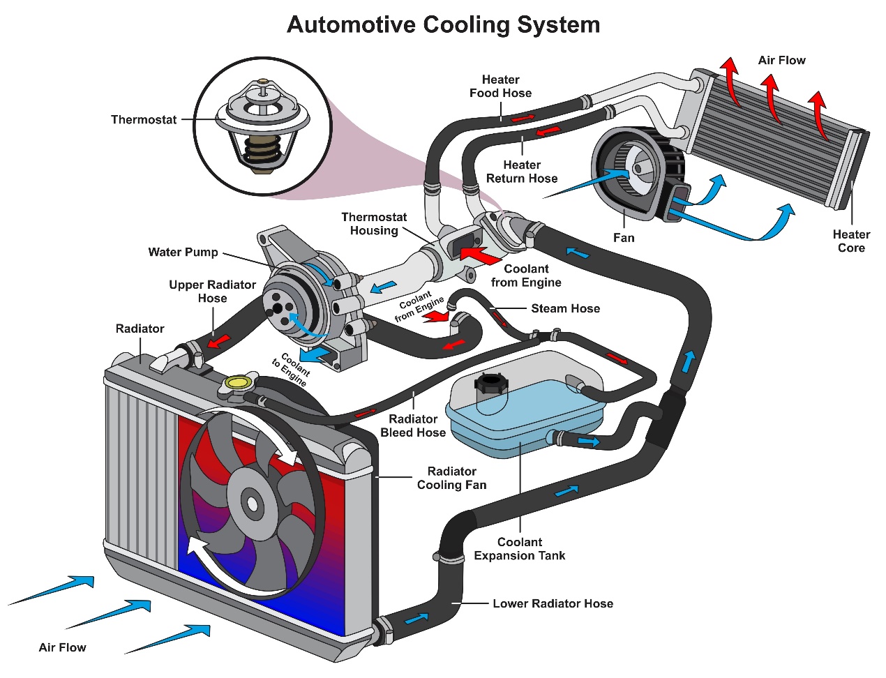
Figure 10 – Automotive Cooling System
On the other hand, when the temperature of the coolant is low, it is heated by a heater, and the thermostat causes the coolant to circulate through the bypass passage instead of the radiator. In this situation, the coolant will only circulate in the water jacket. When the temperature is hot enough and reaches a suitable level (usually set at around 80°C), the heater is turned off, and the thermostat opens, causing the coolant to go through the radiator again.
In this application, mechanical pumps were mainly used in the past. As automotive applications were developed to target high performance and fuel efficiency, some new functions were added, such as idle-stop, sailing stop, and coast stop. When the engine is rotated at a low speed and high load status (the air conditioner is running during vehicle idling), the cooling system becomes inefficient due to the low rotation speed of the engine, and the engine may overheat.
Therefore, the engine's cooling system cannot meet today's automotive requirements with mechanical water pumps. In current designs, an electronic water pump is added to the engine cooling system as an auxiliary pump. An electronic water pump is sometimes used to replace the mechanical pump completely. Figure 11 is a cross-sectional view of an engine cooling system.
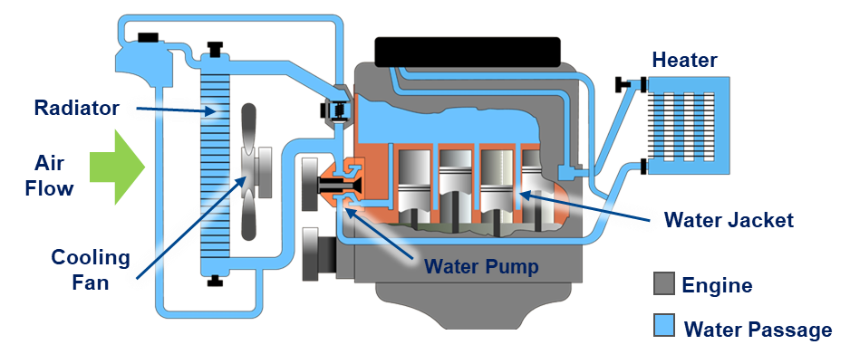
Figure 11 – Cross-section of Engine Cooling System
Figure 12 is an example of the cooling system of the engine of a hybrid electric vehicle. The cooling system of the motor and other electronic parts are separate, as their working temperature is lower. Using the same cooling system across different electronic devices (for example, sharing the system with the inverter that provides electrical energy to the motor) is common. The hybrid car usually has at least two sets of the cooling system.
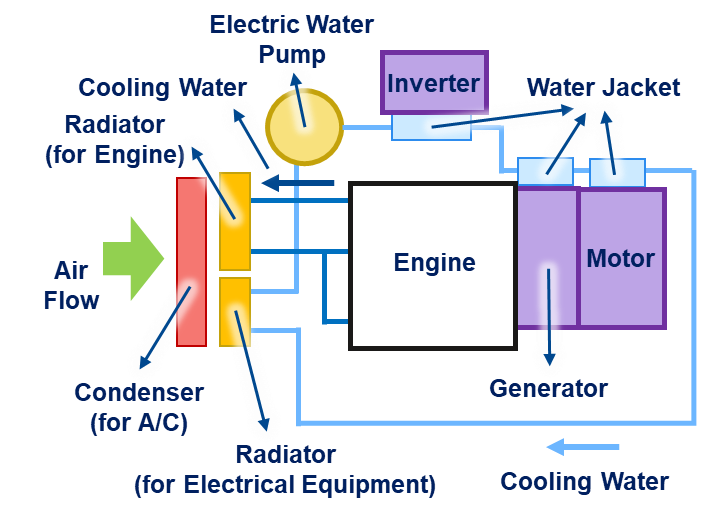
Figure 12 – Hybrid Car Cooling System
Figure 13 shows the structure of the drive motor. As with other types of motors, it comprises a stator and rotor, and an ECU controls its operation. Unlike motors used for other purposes, drive motors have a cooling jacket surrounding them due to high power consumption.
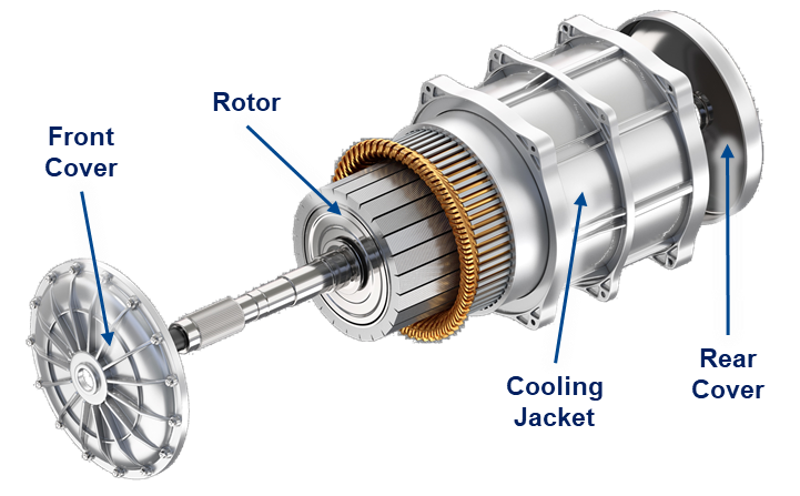
Figure 13 – Drive Motor Structure
Figure 14 shows the cutaway section of the cooling jacket. There is a water passage in the outer case of the motor. The structure and principle of the cooling system are similar to what was discussed for engine cooling.
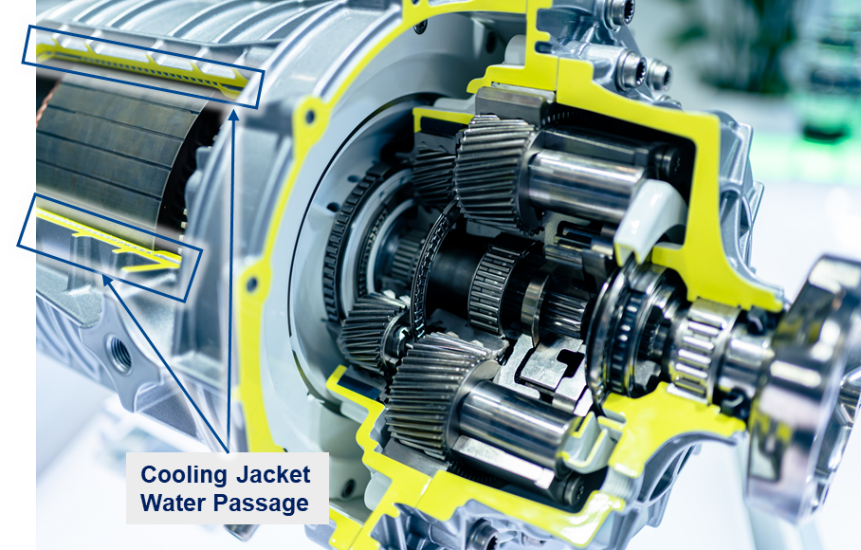
Figure 14 – Cooling Jacket Cutaway Section
A motor is generally designed at an operating temperature of about 23°C, much lower than the engine temperature. However, it still needs a cooling system because heat is generated by the motor itself caused by power loss. The higher the motor's power (higher current), the more heat is generated.
In hybrid cars, the drive motor is installed close to the engine. Therefore, the engine's heat will also raise the drive motor temperature. The higher temperature will increase the DC resistance (RDC) of the winding set in the motor. In contrast, the permeability of the magnetic materials used in the motor (ferrite, permanent magnet, etc.) will decrease. These two points will reduce the efficiency of the motor. So, a cooling system is used for the motor and is designed to keep the system temperature at around 23°C.
The ideal temperature range for EV lithium-ion batteries is about 20°C~30°C. Battery temperature should be monitored and adjusted to stay in this range. If the temperature exceeds this range, the efficiency and life of the battery will be adversely affected. In severe cases, it will even affect the safety of the battery. Generally speaking, the battery's performance deteriorates when the temperature exceeds 30°C. Temperatures above 40°C may cause severe damage to the battery. Heat may destroy the battery cell at higher temperatures, such as 70°C~100°C. Heat is generated from the battery pack, not only in a high workload status (discharging) but also when it is charging (especially when it is quick charging). Therefore, a cooling system is necessary for the HV battery.
Based on battery capacity, car manufacturers will use different cooling system solutions. A few common methods are introduced here. Natural air cooling is generally adopted for batteries with a smaller capacity (See Figure 15).
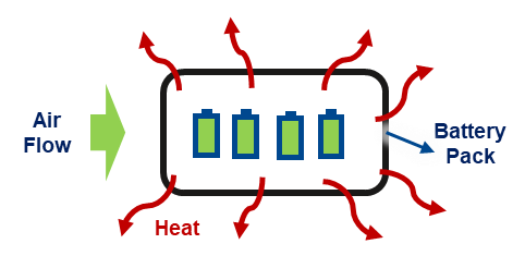
Figure 15 – Natural Air Cooling
This solution has a simple design and is low-cost. But because the battery cooling temperature cannot be lower than the outdoor air temperature, and the cooling cannot be actively controlled, this method will not work with larger capacity batteries and more complicated situations. As a solution, air from the air conditioner is used as active cooling (See Figure 16).
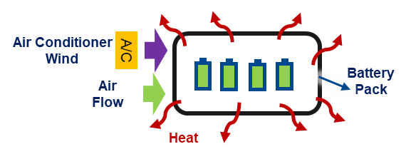
Figure 16 – Natural Air Cooling and A/C Air
Another method is water cooling. The principle is the same as the cooling system for the drive motor discussed earlier, it uses LLC as a coolant, and a water pump drives the system. The motor and other electronic parts sometimes use the same cooling system (See Figure 17).
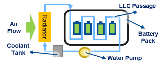
Figure 17 – Water Cooling
The water cooling method is improved by adding another water passage to let the LCC through the air conditioner evaporator to strengthen the cooling effect (See Figure 18).
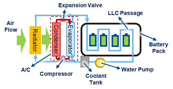
Figure 18 – Water Cooling and A/C Support
Another method is to use the same cooling condenser as the air conditioner. This method uses refrigerant to replace LLC as the coolant and a condenser as the radiator.
This solution is the most powerful cooling system compared with the other solutions discussed (See Figure 19).
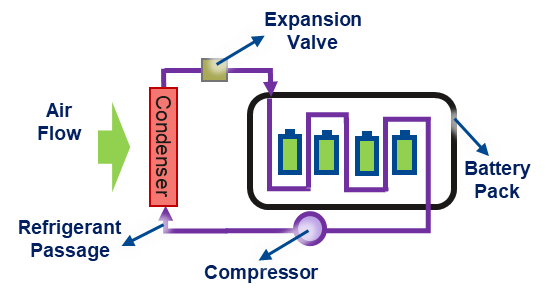
Figure 19 – Refrigerant Cooling
A pump or a compressor is used in the cooling system except for natural air cooling. Different power pumps are selected for different design needs.
After going through some application examples of pumps, it can be concluded that electronic pumps are necessary for modern cars. Some applications require pumps to work in high environmental temperatures, especially for engine cooling and fuel systems.
For the pump motor, DC brushed motors and DC brushless motors are commonly used in automotive pump applications (sometimes other types of motors are also used). Because 3-phase DC brushless motors are more commonly used today, it will serve here as an example. Figure 20 shows a diagram of a DC brushless motor (not including the A/C compressor, which uses high-voltage operation).
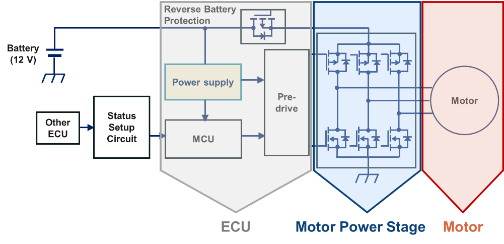
Figure 20 – Pump Motor Circuit Diagram (DC Brushless Motor)
Generally, the low-voltage battery of a car is either 12 V or 48 V. With different designs, 24 V and 36 V are also used sometimes. Since 12 V and 48 V are the primary voltages today, 12 V is used as an example.
Electronic pump systems have three main parts: the ECU, the motor power stage, and the motor. MCU is the motor controller that controls the average voltage and current power stage by switching the transistors on/off at different times. The MCU controls the motor output power (rotation speed x torque). It also communicates with other ECUs through the car network, such as CAN/LIN, receives the data coming from the sensors, and determines how to control switching timing. In general designs, its componentry uses 1.8 ~ 5.5 V, so a DC/DC converter in the power supply circuit transforms the 12 V to 1.8 ~ 5.5 V. A power inductor is needed for this application.
The 12 V input to the motor power stage from the battery supplies power to the motor. The motor ECU controls its input/output power. In this example, a PWM circuit is used.
Pump motor designs have different output power for different purposes. The motor wattage shows the motor's maximum power and determines its maximum workload. In automotive applications, the range is around 20 ~ 500 W. Popular pump wattages are shown in Table 2. With the equation P = VI, we can estimate the maximum average current of the motor in each voltage system.
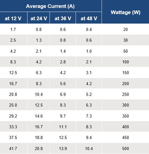
Table 2 – Popular Pump Wattages
The EMI of the pump system is mainly generated from two parts: the motor itself and the PWM controller and its power stage
One or more sets of coils are used to compose the rotor or stator of the motor. So, the motor is an inductive load. Therefore, the equations for calculating the inductance and voltage can be applied to the motor.
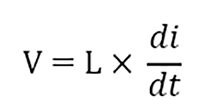
Equation 1
From this formula, one can see that the voltage generated is equal to the inductance value multiplied by the change in current divided by the change in time. Given a constant L value (fixed by motor coil sets), a larger change in current in a shorter time, the greater the voltage generated. Therefore, when the motor is started and stopped, the current changes instantly, which generates a large voltage at both ends of the motor. If this voltage is not handled well, it will affect other electronic components through the circuit and cause them to operate incorrectly or burn. This effect on voltage is called noise, and this common noise source can be seen in every type of motor.
DC brush motors have a unique noise source compared to other types of motors. Figure 21 shows the structure of a brush motor. The commutator mechanism of the motor is a switch that makes the current through the coil switch directions when the motor rotates so that the motor can rotate in the same direction continuously. In this process, each commutator and brush will contact and separate once for each rotation, which can cause a high voltage and thus sparks. This high voltage will transmit to the system circuit as noise.
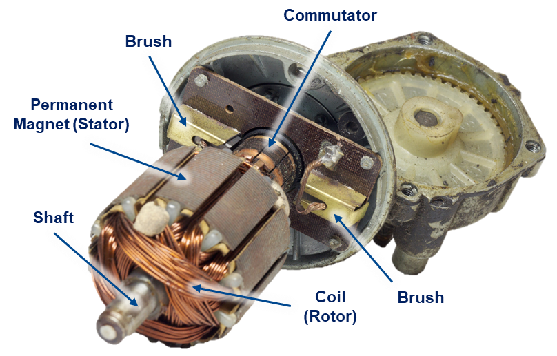
Figure 21 – Brushed Motor
PWM is a technology that controls the power supply ratio by switching on/off the transistor to control the average power (W) to the load. In other words, it uses a smaller current signal to control a larger current power. Because the structure of each type of motor is different, different PWM circuits are used. DC brushed motors generally use H-bridge PWM, while DC brushless motors use 3-phase PWM. Figure 22 shows a DC brushless motor structure.
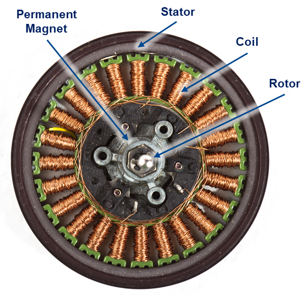
Figure 22 – Brushless Motor
Figures 23 and 24 detail the PWM diagram of these types of motors.

Figure 23 – H Bridge
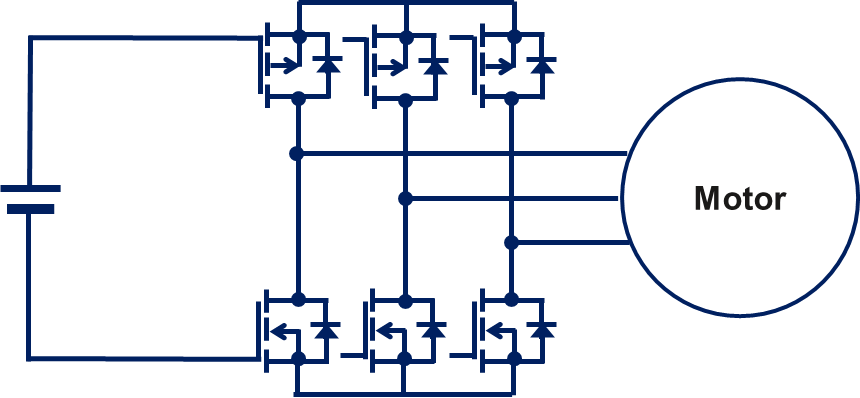
Figure 24 – 3 Phase PWM
No matter the PWM method, some transistors will be switched on/off once or several times for each motor rotation. Each transistor switch will also cause instantaneous changes in current and voltage, which form electromagnetic noise. So, PWM is a noise source.
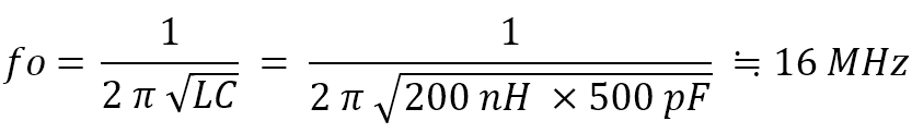
Equation 2 – LC Resonance Calculation
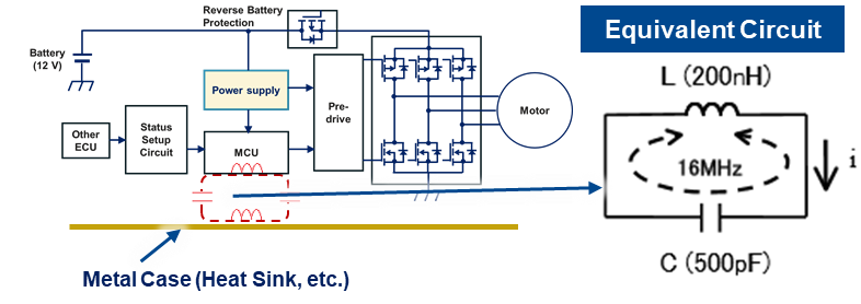
Figure 25 – Inductance and Capacitance Examples of an LC Circuit
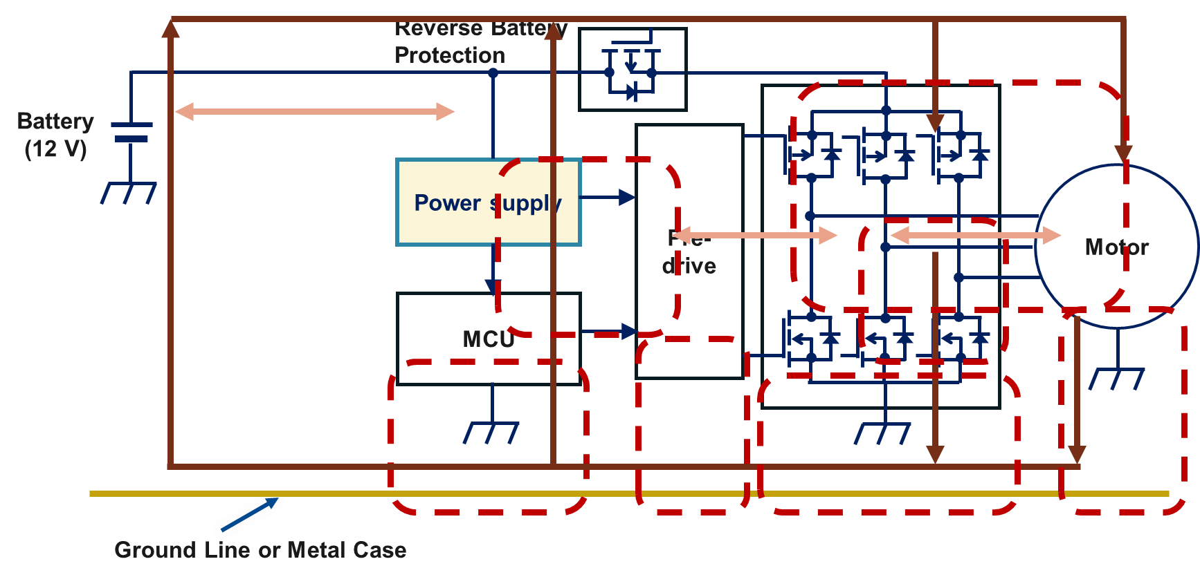
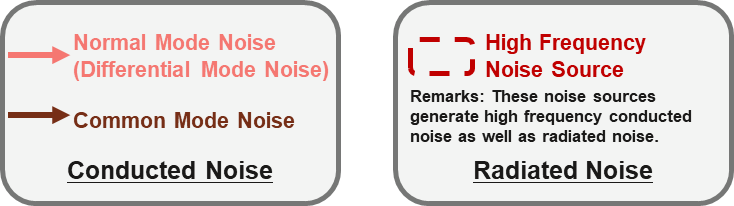
Figure 26 – Conducted and Radiated Noises
In this example, noise is transmitted in three different ways:
If these noises are not dealt with properly, unpredictable incidents and losses may occur. Some car manufacturers have recalled their products from the market because of EMI issues. For example, when a car engine is restarted after idling, the noise generated from the fuel pump motor could be transmitted to the ECU. The ECU falsely detects it as an overcurrent, determines a failure, and stops the fuel pump operation forcibly.
There are many ways to improve pump motor EMI. According to the principle of noise generation, the classification of EMI countermeasures can be roughly divided into three categories:
Theoretically, reducing the noise level from the sources is the best way to counter EMI. However, it is only sometimes possible to do this. In this case, one must think about filtering and changing or blocking the noise transmission path. Figure 27 shows some methods commonly used.
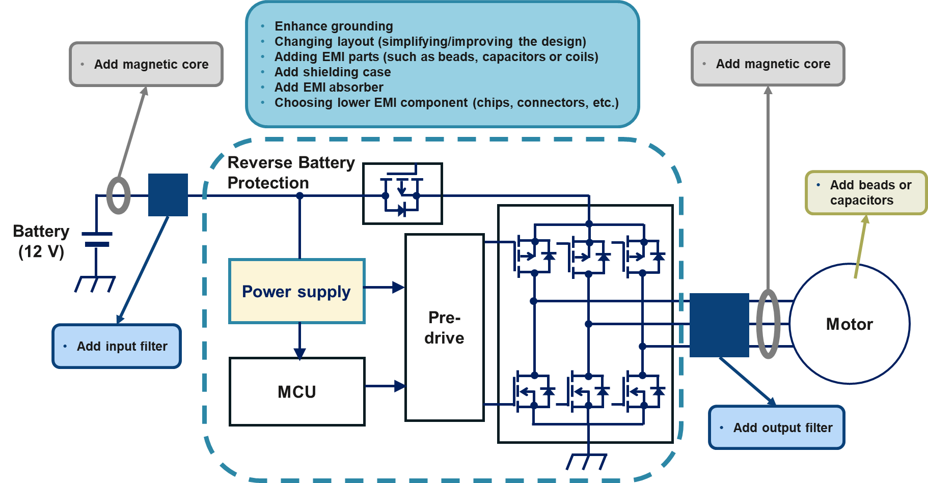
Figure 27 – EMI Countermeasure Methods
Because EMI countermeasure is a broad topic, every method cannot be introduced. We will focus on methods that would require KEMET METCOM inductors.
One of the most effective EMI noise countermeasures methods is adding input/output filters. The blue boxes in Figure 27 and Figure 28 show a typical LC filter diagram. It comprises X capacitors, Y capacitors, a common mode choke coil, and a differential mode choke coil. Because of their distinct characteristics and their position in the circuit, these components impact the high-frequency/low-frequency part of common/differential mode noise. There needs to be a clear boundary between high frequency and low frequency. For convenience, we define high frequency as 5 MHz and above.
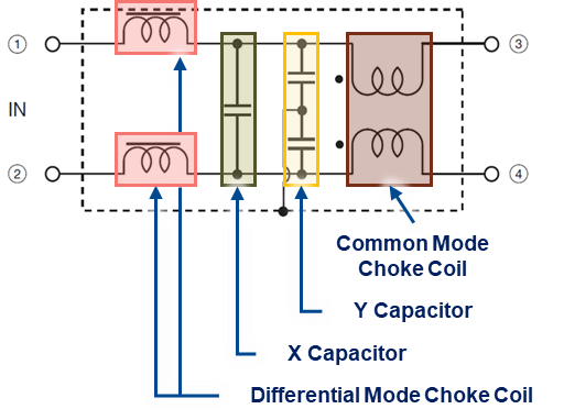
Figure 28 – Typical LC Filter Diagram
Table 3 shows the frequency range and noise mode targeted for each component type within the filter. KEMET’s METCOM inductors can be used as a differential mode choke coil in an LC filter.
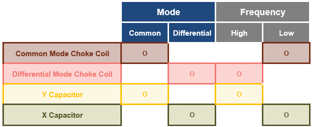
Table 3 – Components’ EMI Effect Overview
Figure 29 is a typical motor conducted noise EMI testing result according to the Voltage method of CISPR Class 3. There are two frequency ranges where this motor is above the test limits: 150~200 kHz and around 12~17 MHz. Generally, low-frequency noise is caused by the start/stop of the motor. High-frequency noise is typically generated by PWM, power supply switching, and high-frequency loop composed of floating/parasitic capacitance/inductance.
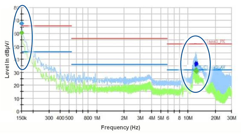
Figure 29 – Typical Motor Conducted Noise EMI Testing Result
In the beginning stages of EMI testing, it is difficult to know whether the noise transmitted is common mode or differential mode. So all four kinds of filtering components (X/Y capacitor and common/differential mode coil) are first used in the LC circuit.
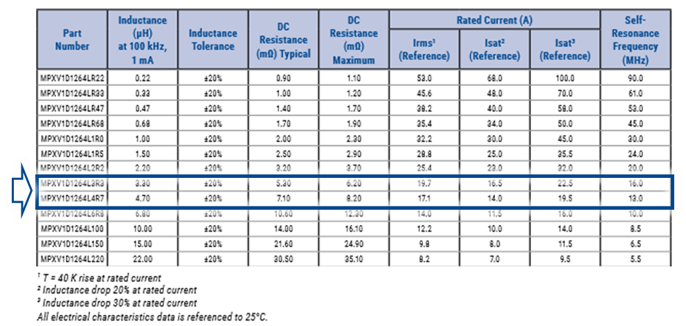
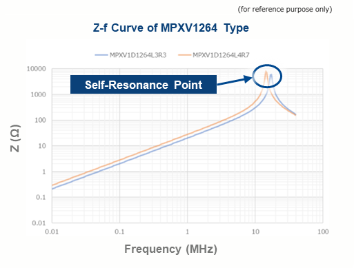
For differential mode choke coil selection, we first need to consider the rated current of the inductor. Take a 12 V 200 W motor as an example. When fully loaded, the average current of the input power line is about 16.6 A. The coil Isat and Irms parameters should be higher than that. An Isat rating that is too low will cause the filter performance to worsen, and an Irms rating that is too low will cause excessive heating of the inductor. For the best performance, it is best to keep a 10~20% margin for these parameters (but it is not a must). In this situation, a 20 A-rated current part number is preferred. The second thing one needs to consider is the impedance characteristic. Generally, at the resonance point of the coil, the impedance reaches the highest point. Therefore, the self-resonance point of the coil can be used as a rough indicator for selecting a differential mode choke coil. Match the resonant frequency to the frequency range where the EMI problem occurs. In KEMET’s METCOM inductors product line, MPXV1D1264L3R3 or MPXV1D1264L3R3 are suitable for this example (See Figure 30).
Because we use impedance only in this application, the L value is just an indicator of impedance.
Because many chips (such as MCU, memory, communication chips, etc.) are used in the electronic controller of the electronic pump, they are generally used at a lower operating voltage. As with other applications, the switching frequency of DC/DC chips is getting higher and higher. Therefore, the current flowing through the inductor in the DC/DC circuit is larger than before. The larger current has led to more use of metal composite-type inductors such as KEMET's METCOM series. Using metal composite inductors can lead to better EMI effects and DC superimposition characteristics than ferrite inductors. Table 4 compares metal composite and ferrite inductors (Follow this link for more information on KEMET’s METCOM inductors here.
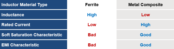
Table 4 – Inductor Material Characteristics
Table 5 shows the difference in rated current between METCOM and ferrite inductors with the same size and inductance value. KEMET’s METCOM inductors rated current is higher than many ferrite inductors. Because of this, one can use a smaller size METCOM inductor to replace ferrite at the same current level.
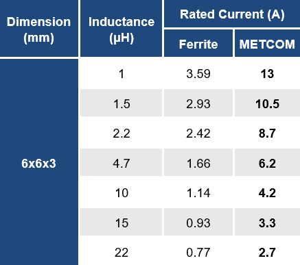
Table 5 – Rated Current Differences Due to Inductor Material
One more topic must be covered to avoid mixing up the concept of using METCOM inductors as power inductors in DC/DC applications compared with using them as a differential mode choke coil. Unlike in an EMI filter, when the inductor is used in DC/DC applications as a power inductor, it should never be used on a circuit that exceeds or comes close to its resonance frequency. The inductor's L value of the power used in the DC/DC is related to the output ripple current of the DC/DC, and the L value needs to be kept in a specific range. Usually, a 30% drop in catalog value is acceptable. However, the L value changes significantly when the circuit frequency is near the power inductor resonance frequency. (See Figure 31). The L value is used in DC/DC usage, but in filter usage, it is not.
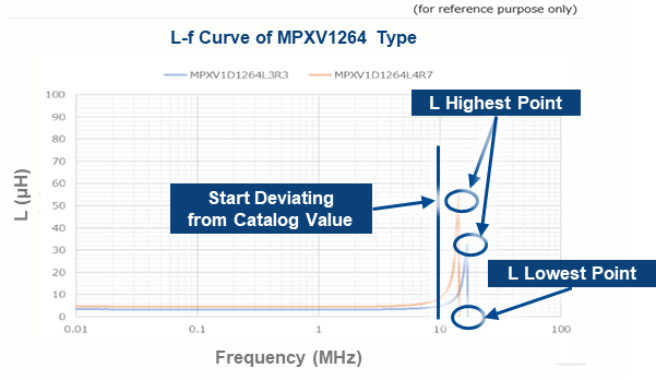
Figure 31 – L-f Curve of MPXV1264 Series
Generally, the value of the resonance frequency point on the datasheet is only a reference value, not a guaranteed value. The tolerance is generally significant. If you need to use it near the resonance frequency as a power inductor, please check with the inductor manufacturer first.
As mentioned above, some pump applications in automotive need to work in high-temperature environments. Especially for engine-related applications, sometimes the pump is required to perform at a working temperature of up to 135°C. One must consider the self-heating of the inductor during operation. The Irms value on the datasheet shows the Irms value at which the inductors self-heating is 40°C. Figure 32 shows a comparison between KEMETs MPEV and MPXV series
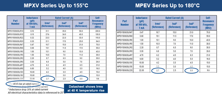
Figure 32 – Comparing MPXV and MPEV
The rated current between the two series seems the same, but when the inductor is used in a high-temperature environment, the MPEV series will withstand the heat better than the MPXV series. For example, using a 22 µH, 2.7 A part with a self-temperature rise of 40 K in an application with 135°C working temperature, the whole inductor temperature will rise to 135°C + 40°C = 175°C. In this case, MPXV parts, which are rated at 155°C, will not be able to withstand this 175°C. To keep MPXV below its limit of 155°C, one would need to reduce the current or choose a bigger size to handle the self-temperature rise of the inductor. That means the Irms current value in the specification cannot be fully utilized in this case. Using MPEV, a KEMET 180°C rated product, one can avoid this kind of problem.
Another important evaluation item for inductors used at high temperatures is the insulation resistance (IR) under a high-temperature environment. The testing method is shown in Figure 33.
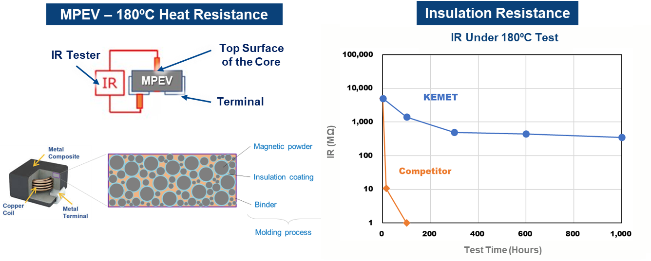
Figure 33 – Importance of Insulation Resistance
Testing is performed using an IR tester to determine the IR value between the terminals and the surface of the inductor after some time under a 180°C environment. KEMET MPEV insulation resistance value is over 200 MΩ. As shown in Figure 33, the competitor product tested was unable to maintain this same insulation resistance. After analysis, we found that the binder in the core of the competitor's product melted, which caused this testing result. So, when selecting an inductor for high-temperature usage, not only does one need to consider the electronic characteristics, but one also needs to consider reliability data, especially for automotive applications.