Every year, over four trillion ceramic capacitors are manufactured for applications ranging from toys, wearable technology, and electric vehicles to satellites. These capacitors perform a broad range of functions such as decoupling, filtering, transient voltage suppression, and many more. For the vast majority of these applications, standard Base Metal Electrode (BME) ceramic technology uses nickel as the internal electrode. In fact, over 99% of ceramic capacitors shipped today use nickel electrode technology. However, there is a subset of applications used today that operate at much higher frequencies, and standard nickel electrode technology is not suitable. This article provides insight into some of the key characteristics of RF capacitors and why they are important for high-frequency applications.
Before we define what an RF capacitor is, we need to provide some background on RF. RF stands for "Radio Frequency" and refers to the oscillation rate of an AC voltage, current, or electromagnetic waves in an electronic device or medium. Today, almost all electronic devices use alternating voltages and currents, ranging from 50Hz to 100s of GHz. RF is a very broad term and refers to frequencies when the AC voltages are above 20kHz. However, in the context of RF applications and RF capacitors, RF is usually referred to with frequencies starting above a few MHz and up. Sometimes, the term “RF” and “High Frequency” are used interchangeably when referring to high-frequency components and applications.
The RF frequency spectrum can be divided into multiple regions (bands) based on the frequency range and target applications. The RF “High Frequency” range can be divided into the "Microwave Band" which ranges from 300MHz to 300GHz and the mmWave (millimeter wave) band which begins at 28GHz. As frequency increases, the wavelength decreases as shown in the figure below. The term mmWave derives its name from the wavelength of the electromagnetic wave being measured in millimeters.
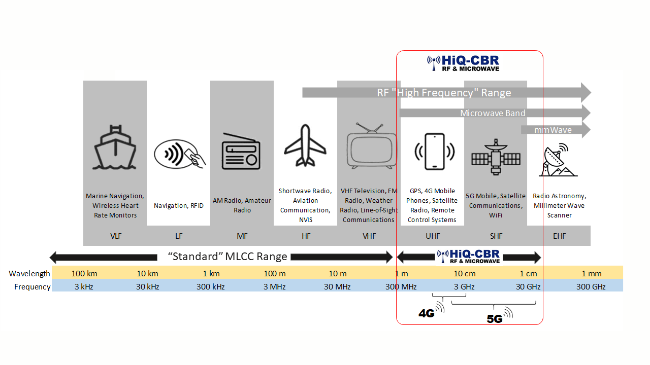
Figure 1 - RF Frequency Spectrum
There are key advantages when increasing the frequency of applications to go higher and higher. By increasing the frequency, designers can make better use of the frequency spectrum allowing more devices to be wireless without causing interference. In addition, increasing the frequency allows for higher bandwidth. Thus, increasing data transmission.
However, there are disadvantages to higher frequencies. These include shorter ranges, signals blocked by dense objects, and signals affected by weather conditions. This is why higher frequency mmWave 5G technology will require more cellular base stations in dense population areas.
RF capacitors are used for various functions such as DC blocking, bypass, filtering, and impedance matching. Common applications include the following:
There are four key characteristics of capacitors needed for RF applications.
This is the resistance of the capacitor which includes resistance due to losses in the dielectric and electrodes. This is important because ESR is directly related to power dissipation in the form of heat. Higher ESR can cause excessive heating in the capacitor, and RF capacitors must have the lowest possible ESR at high frequencies.
Power Dissipation = i2 * ESR
To achieve low ESR in a ceramic capacitor, the dielectric and electrodes must be optimized to have the lowest possible losses. For the dielectric, RF capacitors are almost always a Class I C0G/NPO material due to their very low loss.
Even more important is the choice of the inner electrode material. Figure 2 shows a comparison of resistance between a 100mm wire made from nickel and the same wire made from copper. The graph shows that as frequency increases above 10MHz, the resistance of the nickel wire starts increasing dramatically while the resistance of the copper wire remains relatively flat. For this reason, copper is the material of choice for Base Metal Electrode RF capacitors.
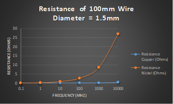
Figure 2 - Resistance of a 100mm wire made from copper and nickel.
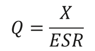
Q represents the efficiency of the capacitor and represents the ratio of energy stored in the capacitor to the energy dissipated as thermal losses due to the equivalent series resistance (ESR). Q is directly related to ESR because lower ESR means higher Q since it’s inversely proportional. RF capacitors have very high Q due to their low capacitance and very low ESR. Therefore, RF capacitors are often referred to as High Q capacitors.
Since RF capacitors are often used for tuning and impedance matching applications, capacitance stability versus temperature is critical. Any change in capacitance with temperature can result in the circuit detuning or becoming unmatched.
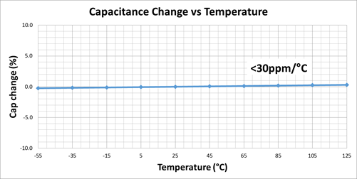
Figure 3 - Capacitance change vs temperature of a Class 1 RF capacitor
SRF shows where the total impedance is no longer capacitive and begins an upward trend. This is known as the inductive region of the impedance curve and is a direct result of the capacitor's Equivalent Series Inductance (ESL). For some applications, it is necessary to stay well below the SRF, so RF capacitors need to have as high an SRF as possible.

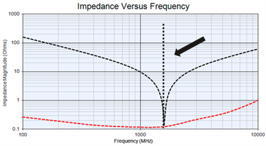
Figure4 - Impedance versus frequency of a Class 1 RF capacitor showing the SRF.
Knowing the four key characteristics of an RF capacitor, a definition can be provided.
Definition: An RF capacitor is a capacitor that's "characteristics" are optimal at RF frequencies.

Therefore, for RF capacitors, materials are chosen, and designs are optimized so that the capacitor’s characteristics are optimal at higher frequencies.
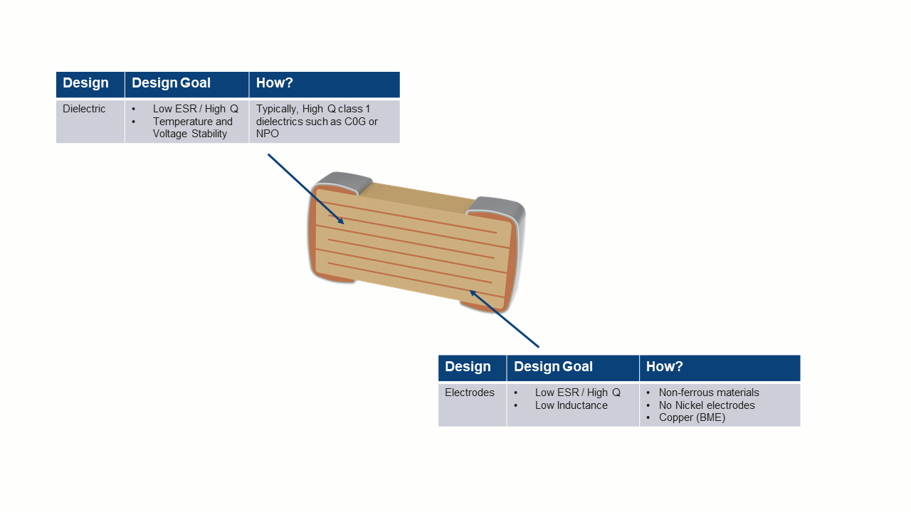
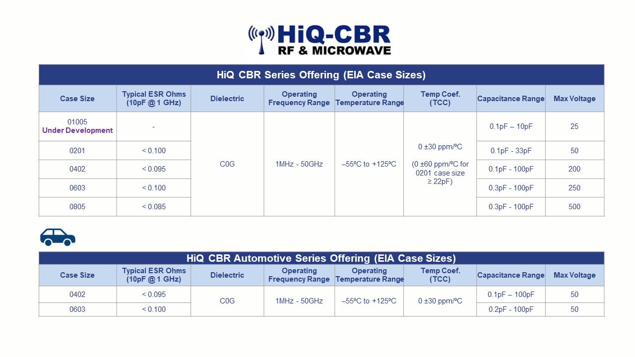
KEMET’s HiQ CBR RF Capacitor Series features a copper electrode BME (Base Metal Electrode) system that offers ultra-low ESR and High Q in the VHF, UHF, and microwave frequency bands. Low ESR allows for higher RF currents which are ideal for various applications. Available in both commercial and automotive grades, these capacitors exhibit very low ESR and high Q along with high SRF making them ideal for applications ranging from 1 MHz to 50 GHz.
