A voltage doubler circuit outputs a DC voltage that is double the peak value of the AC input voltage, without using a transformer. There are many electrical design situations where an AC voltage signal is available (or can be created), but a larger DC voltage is needed for the circuit. These situations include energy harvesting, high voltage flashers, or ion generator applications. Transformers are often the first thought for engineers confronted with the need to multiply voltage, but a well-designed voltage doubler circuit can be the better solution in many cases.
The most simple voltage doubler circuit is a half-wave doubler, and it is nothing more than a series capacitor with a reverse biased diode to GND. This is also called a Villard circuit, named after its inventor.
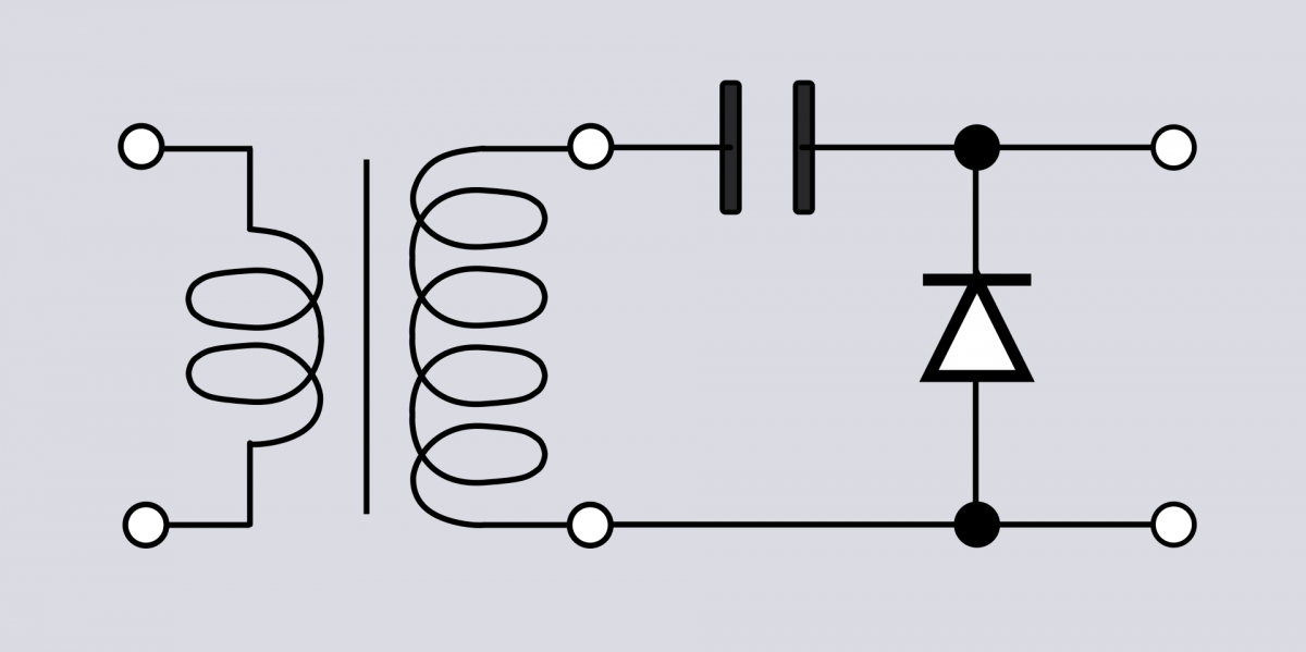
Figure 1: Half-Wave Voltage Doubler Circuit (Image: Wikipedia) (https://en.wikipedia.org/wiki/Voltage_doubler)
The capacitor allows AC current to pass through it, but the diode only allows current to flow in one direction. This creates a peak output voltage of 2*Vpk across the diode. This extremely simple circuit illustrates the concept, but it does not regulate the output DC voltage very well:
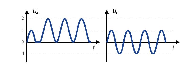
Figure 2: Input and Output Voltages of a Half-Wave Voltage Doubler (Image: KEMET)
It should also be noted that a voltage doubler is the first-order form of a voltage multiplier. Voltage multipliers can be stacked together to triple a voltage, quadruple a voltage, and so on.
A more common and sophisticated voltage doubler circuit is the full-wave voltage doubler, or Delon circuit, which uses two diodes and two capacitors to provide a doubled DC voltage output.
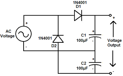
Figure 3: Delon Voltage Doubler Circuit (Image: KEMET)
This circuit is, essentially, two stacked peak detector circuits, each charging their respective capacitors during opposite halves of the incoming AC voltage signal.
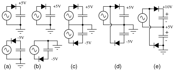
Figure 4: Full-wave doublers: (a) Pair of doublers, (b) redrawn, (c) sharing the ground, (d) share the same voltage source. (e) move the ground point. (Image: All About Circuits) (https://www.allaboutcircuits.com/textbook/semiconductors/chpt-3/voltage-multipliers/)
The output voltage is then a DC voltage approximately equal to the peak-to-peak voltage of the incoming AC voltage, or 2*Vpk, or 2*Vin*√2:
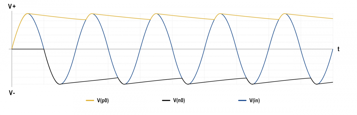
Figure 5: Voltage doubler input / output voltage waveforms (Image: KEMET)
In this plot, the blue line is the incoming AC voltage, the black line is the output GND (-), and the yellow line is the output Vout (+). During the very first half cycle of the incoming AC voltage sine wave, C1 charges from current passing through D1. During the next half cycle, C2 charges in reverse, while C1 discharges. In the third half cycle, C1 charges again up to the peak voltage, while C2 discharges, and the circuit has reached steady state operation.
The output voltage ripple depends primarily on the characteristics of the capacitors used and the load on the output. Capacitor selection is the most important task, then, when designing voltage doubler circuits.
Selected capacitors should have good energy density and capacitance-voltage (CV) while remaining cost-effective. The capacitors must be selected to provide the current required by the load.
Aluminum electrolytic capacitors are an obvious choice, providing excellent energy density, CV, and cost. Electrolytics like KEMET’s ALC40 series have a long life at elevated temperatures, making them ideal for voltage doubling applications. However, there are a number of factors engineers should carefully consider for these designs:
An ideal capacitor introduces zero resistive effects to a circuit. Real-life capacitors are not ideal, however, and do introduce resistive components. The most important of these effects is the equivalent series resistance (ESR). This resistive component is primarily what causes it a capacitor to dissipate power, which creates heat and shortens its life span.
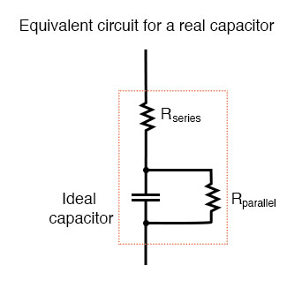
Figure 6: The Ideal Capacitor (Image: All About Circuits) (https://www.allaboutcircuits.com/textbook/alternating-current/chpt-4/capacitor-quirks/)
AC current through a capacitor dominates the heat generated by a capacitor. In the case of a voltage doubler, the AC component of the voltage on the capacitor is the ripple voltage. The frequency of the AC signal is another factor, where a higher frequency will generate more heat. And finally, a portion of the current the capacitor supplies from its stored energy to the load is also lost to heat, so higher current load applications generate more heat.
The Maximum ESR for the ALC40 series aluminum electrolytic capacitors ranges from 6mΩ to 1,000mΩ depending on the voltage, capacitance, and size of the capacitor. Minimizing ESR to the lowest ESR that supports the design is always recommended.
The load supplied by the output is another critical item for a voltage doubler because the output is poorly regulated. With a resistive load, a higher current causes more voltage decay between voltage peaks, causing the DC voltage to sag and the ripple voltage to increase. The power output of a voltage doubler is limited by the input power and the efficiency of the circuit. So the maximum theoretical output current of a voltage doubler is half the input current. Because of this, voltage doublers are not ideal for high continuous power applications. Rather, they are good for loads that require high voltage charges, but not high power.
In the case of an inductive load, the reactive characteristics of the load can cause a reverse bias voltage to feedback to the voltage doubler. Aluminum electrolytic capacitors are polarized and can suffer catastrophic failure when reverse biased, which is often a concern when they are used to drive inductive loads. Most electrolytic capacitors can withstand a small reverse voltage up to -1.5V or -2.0V, for a short period of time. The ALC40 series from KEMET, for example, can withstand up -2.0V reverse bias voltage before cathode oxidation starts to occur. The voltage doubler circuit presented here is inherently protected against capacitor damage from reverse biasing by the two diodes, which will clamp the reverse voltage to a maximum of two diode drops, or approximately -1.4V.
Whenever aluminum electrolytic capacitors are used to store and supply energy, calculating the expected lifetime is crucial. The primary factor in electrolytic capacitor lifetime calculations is temperature, and many factors influence capacitor temperature. Operating temperature, ripple current, DC voltage, load current, and frequency all play a role. KEMET offers a simple online tool called the Aluminum Electrolytic Capacitor Life Expectancy Calculator to help with these calculations. This tool performs life calculations based on an operating temperature method or a ripple current method and calculates temperatures and life expectancies for specific conditions.
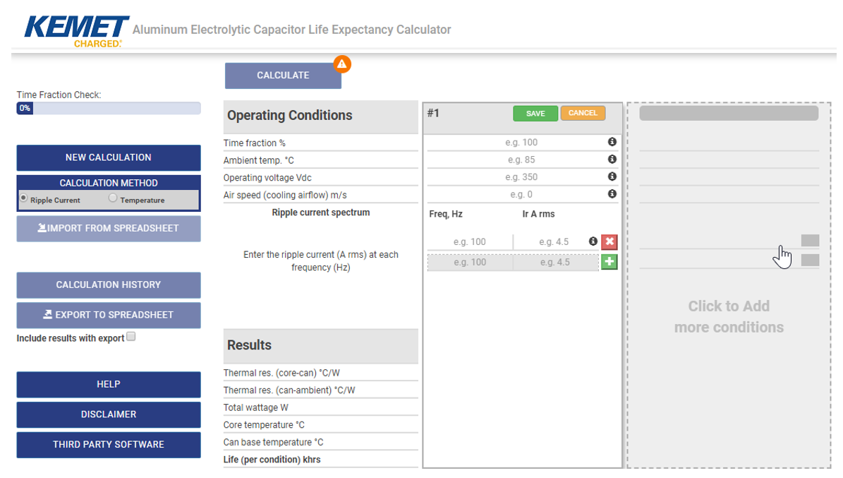
Figure 7: KEMET’s Aluminum Electrolytic Capacitor Life Expectancy Calculator (Image: KEMET)
Engineers don’t have to design voltage doublers from scratch. KEMET has application engineers willing to design custom solutions for any application and assist with the load calculations, life expectancies, and capacitor selections.