From watches and phones to electric vehicles, wireless power transfer (WPT) systems for charging batteries are becoming ubiquitous. Wireless power transfer offers many advantages, including the elimination of power cords and the increase of safety and durability.
Automotive applications always require special care, and WPT in electric vehicles is no exception. Reliability and safety are both critical for users and regulated by third parties. So properly understanding, selecting, and using components is of the utmost importance.
In electronic circuits, a resonant circuit is formed whenever an inductor (L) and capacitor (C) are connected. The values of the L and C form a resonant frequency, which is the frequency at which the circuit will resonate, continuing to oscillate on its own after an initial introduction of energy.
Frequency of an ideal resonant circuit:

In an ideal circuit, this resonating circuit would continue to oscillate indefinitely, but in real life there are impedances involved in every real circuit that won’t allow perpetual resonance. But resonant circuits still have a lot of value when it comes to wireless power transfer circuits.
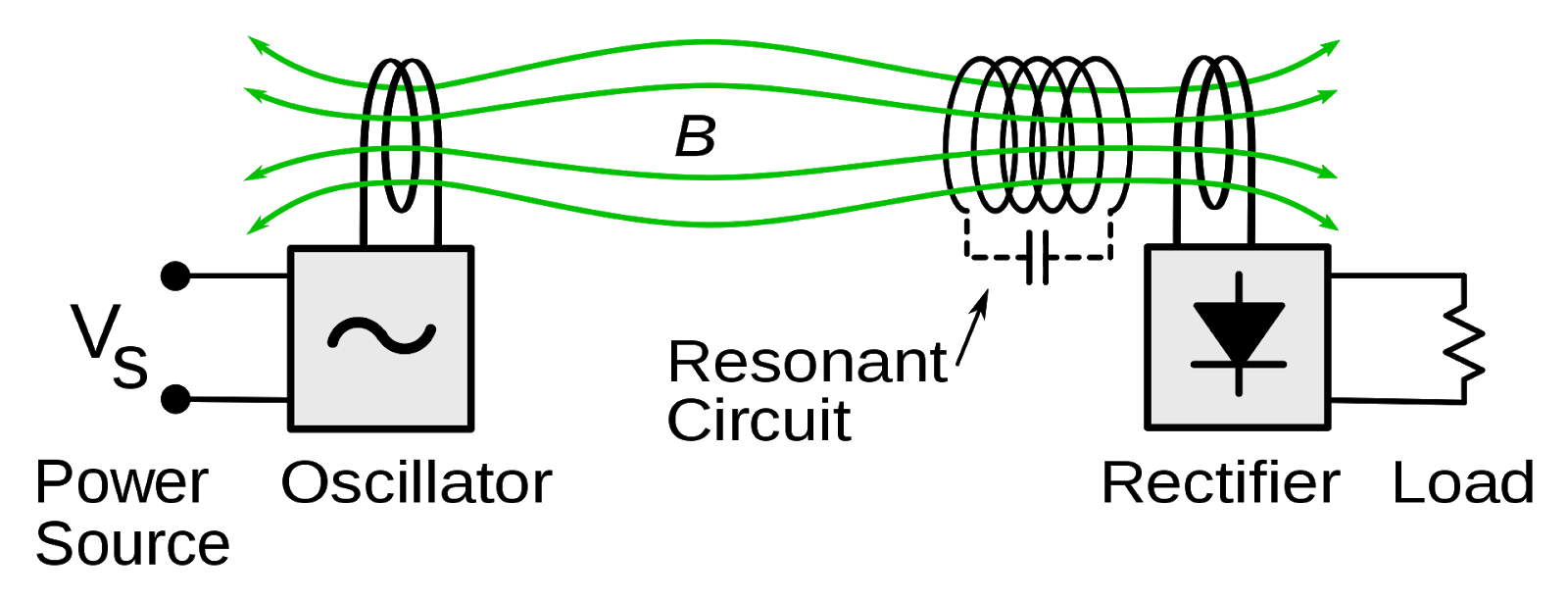
Figure 1: A Basic Resonant Inductively Coupled WPT
In its most basic form, a wireless power transfer resonant circuit works by powering an oscillator that is inductively coupled to a resonant circuit in the target device. That resonant circuit causes the inductive coupling to strengthen, creating a higher efficiency power transfer. That transferred power is then rectified and used by the load in the target device.
More advanced versions of WPT resonant circuits use a resonant circuit on both the source and load sides or have other improvements and advanced designs, but the basic fundamental concept of the resonant circuit for WPT remains the same.
WPT applications require capacitors with very stable capacitance versus temperature, voltage and time. In addition, these applications can generate high AC currents which can cause excessive heating in lossy components. Class I C0G and U2J Multilayer ceramic capacitors (MLCCs) are ideal for WPT circuits as compared to Class II MLCCs and other capacitor technologies. Class I MLCCs have very stable capacitance versus temperature, voltage, and time and have very high ripple current capability versus other technologies. The below figure shows the benefits of Class I C0G and U2J dielectrics compared to Class II X7R.
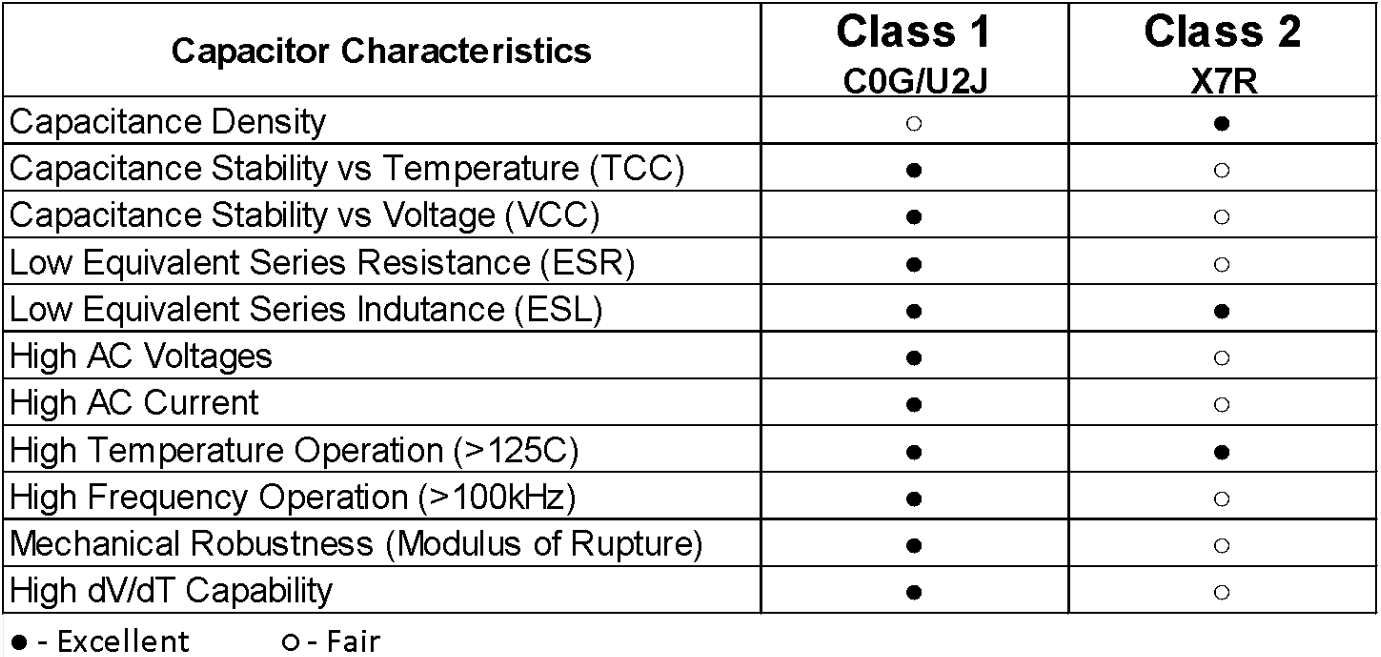
Figure 2: Key Characteristics Comparison Between Class II X7R and Class I C0G/U2J
In many WPT applications, the capacitance, AC voltage, and AC current requirements are beyond what a single capacitor can provide. Therefore, it is common to have a series/parallel combination of MLCCs to achieve the application requirements. For example, adding MLCCs in parallel will increase the overall capacitance and AC current handling capability. Adding MLCCs in series will decrease the overall capacitance and increase the AC voltage capability. And using a series/parallel combination can provide an overall capacitor solution capable of handling very high-power levels. KEMET offers tools to help designers optimize the number of MLCCs in parallel and series to meet application requirements.
Let’s look at an example design. For this design, we will be designing the capacitor selection for a WPT resonant circuit for an electric vehicle charging system.
For this system, we will need to select the appropriate KEMET capacitor for a WPT system defined as follows:
Although this application is strictly using AC voltage, MLCCs do not have an AC voltage rating. Therefore, we must determine the minimum MLCC DC voltage rating required for the application. To determine the minimum DC voltage rating needed for the capacitor, there are two rules that both must be satisfied:
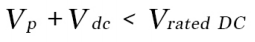
Rule #1 is that the DC rating of the capacitor must be larger than the peak AC voltage plus the DC voltage in the application. Basically, the peak voltage can never exceed the rated voltage of the MLCC.
Rule # 1
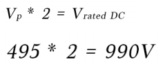
The peak AC voltage (Vp) can be calculated using the equation below.
Back to Rule #1:
495 + 0 = 495
So to satisfy Rule #1, the DC rated voltage must be greater than 495V
Rule #2 is that the peak AC voltage (Vp) must be less than half the rated DC voltage. You can also convert this to RMS and say that the AC RMS voltage must be less than the MLCC rated voltage divided by two times square root two.
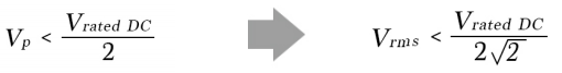
Rule #2
We can use the peak voltage of the AC waveform to calculate the minimum DC rating of the capacitor network:
So, to satisfy Rule #2, the DC rated voltage of the capacitor network must be greater than 990V.
By looking at both Rule #1 and Rule #2, we see that the capacitor network rated voltage must be greater than 990V (which is the greater of the two rules).
Now that we know the required capacitance (66nF) and DC voltage rating (> 990V) for our WPT resonant circuit application, we need to find a suitable capacitor. KEMET’s KC-LINK capacitors are ideal for resonant applications, so let’s look at their offerings. The following table is from the KC-LINK datasheet, found here.
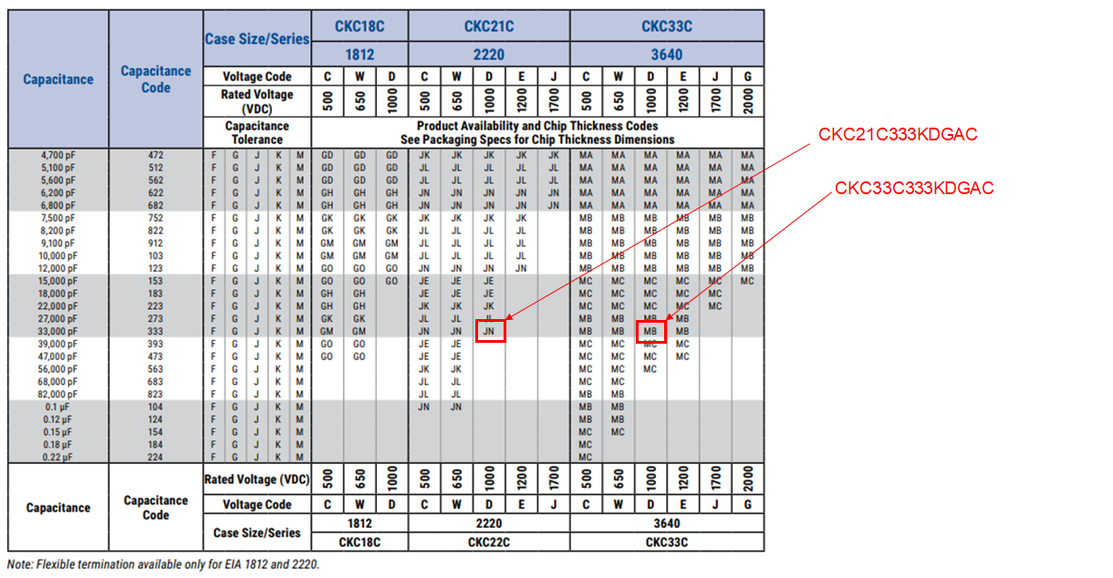
Figure 3: KEMET’s KC-LINK Waterfall Component Selection Table
While KEMET’s KC-LINK capacitors are ideal for resonant applications, there are no 66nF capacitors available rated for > 990V. However, there are two options for 33nF capacitors rated at 1000VDC, as shown in the table, in package case sizes 2220 and 3640.
Now that two possible capacitors have been identified, we must determine the ripple current capability of each to see if either will work in our application. Using KEMET’s free online circuit simulator, K-SIM, we can simulate the ripple current in each device:
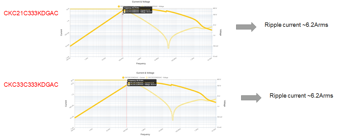
Figure 4: Simulations to Determine Ripple Current of Possible Capacitors
For each of the capacitors under evaluation, the ripple current is ~6.2Arms. By placing two of these capacitors in parallel, the total capacitance will be 66nF with an AC current of 12.4Arms which meets our application needs.
Two other considerations when analyzing a capacitor’s voltage and current ratings in AC applications are their operation in the voltage-limited and current-limited regions.
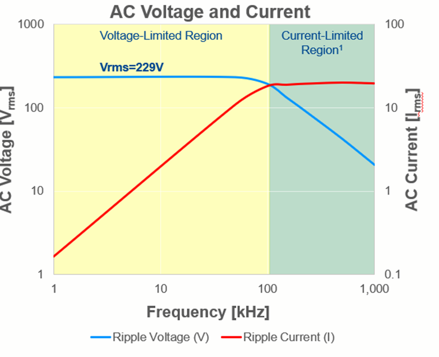
Figure 5: AC Voltage and Current Ratings vs Frequency
As demonstrated in the sample graph, at lower frequencies the voltage rating is the limiting factor, while at higher frequencies the current rating is the limiting factor. At a certain frequency, there is a crossover point.
In the voltage-limited region, the primary risk to MLCCs is breakdown or damage due to high AC voltages. Proper capacitor selection and derating for the operating environments and conditions are important to ensure reliable operation in this region.
In the current-limited region, the primary risk to MLCCs is breakdown or damage due to self-heating due to i2R losses. Every real-life capacitor has an equivalent series resistance (ESR) and as frequencies and/or capacitance increases for the same AC voltage, the AC current increases through the capacitor. For this reason, it is again critical to select capacitors with low ESR and derated them properly for the application
KEMET offers a patented technology called KONNEKT that allows two, three, or four ceramic capacitors to be stacked vertically without using any metal strips on the sides. This technology utilizes a transient liquid phase sintering process (TLPS) and can be mounted using traditional reflow processes.
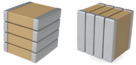
Figure 6: KONNEKT Technology for Stacked SMD Capacitors
Stacking ceramic capacitors on top of each other is a way to solve the problem of tight spaces. Because of the increasing miniaturization of electronic devices and the requirements for smaller electronic components with more capabilities, higher ratings, and robust reliability, a smaller footprint on a circuit board is critical. Traditionally, components are stacked on top of each other to conserve space and to hold them in place, using metal beds – or lead frames. However, lead frames are costly and introduce power loss. KEMET KONNEKT technology creates a low loss, low inductance package capable of handling high temperatures and high power while taking up a very small footprint on the board.
For wireless power transfer (WPT) resonant circuits, KEMET’s KC-LINK capacitors, stacked together with their patented KONNEKT technology, offer an ideal solution. WPT resonant circuits used to power and charge electric vehicles are likely to become more common, and more advanced and improved solutions are on their way. KEMET technologies will be there every step of the way.