For decades, the standard ports on a piece of electronic equipment included a power plug of some variety and a data port. In the world of personal computing, especially in the mobile space, the power plug was often a circular connector for DC and the data port was a D-sub serial or parallel connector. Accessories communicated over these data ports and often had their own DC power supply or batteries.
In 1996, the USB 1.0 standard was officially released, and it represented an attempt to redefine data communication with PC accessories by adding power delivery to the feature list. By 1998, the first mainstream products included USB 1.1 ports, but many held on to their legacy serial and parallel ports for backward compatibility. USB 1.1 offered a 12 Mbit/s data rate (a nearly 100x speedup over the fastest serial ports of the time) as well as 9W of power delivery at 5V.
Since then, the data rates and power delivery characteristic have continually improved. Today’s latest standard (USB 4.0) boasts 40 Gbit/s of data and 100W of power using the new USB-C connector. These figures are truly game changing and have a direct impact on the industrial design of technology products and their potential capabilities.
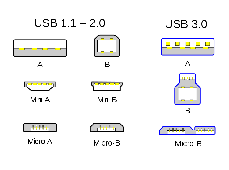
Is is also important to note the difference between the USB standards and the USB physical connectors. The connectors we have grown familiar with (Type A, Type B, Mini, and Micro) support standards from USB 1.0 through USB 2.0. Two varieties of Type A and Type B were then added with 5 extra pins to support the USB 3.0 standard.

Figure 1 – Type-A, Type-B, Mini-A and Mini-B, and Micro-A and Micro-B USB connectors. Source: Wikimedia Commons
In general, these “traditional” USB connectors all contain a ground, a 5V power pin, and two differential data pins. The five pin connectors have an additional “ID” pin to identify the host versus the device. In all cases, the connectors were unidirectional for power (host to device), have specific genders for device types, and were rotationally polarized to only fit in one orientation.
USB-C actually refers to a type of USB connector introduced in 2014 with some pretty remarkable specifications. Physically, the connector contains 24 pins, measures 8.4 mm x 2.6 mm, and is rotationally symmetrical with well-defined genders: cables are male and devices are female. From the user perspective, this elegant form factor results in a very simple and rugged interface.

Figure 2 – The physical layout of a USB-C connector. Source: Wikimedia Commons
Under the hood, the connector itself can support a range of USB standards, from USB 2.0 through USB 4.0. However, just because a device has a USB-C connector does not mean that it supports any specific standard. A USB 2.0 device may only use the two differential D pins, power and ground. This is largely accomplished through the use of two configuration control (or “CC”) pins that allow the attached devices to monitor for connections, establish roles as sources or sinks of power, configure the power delivery parameters, and determine cable twist for data bus routing.
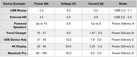
USB-C takes power delivery to a whole new level. Whereas previous USB standards were targeted at USB charging, the new USB-C connector is designed to deliver up to 100W of power for a wide range of peripherals. This power is also directionless and can flow from host to device or vice-versa. This article, in fact, was written on a MacBook Pro connected to a 4K display over USB-C. The typical 87W of charging power is flowing from the monitor to the computer, while incredibly high data rates are flowing from the computer to the display. It’s a truly eye-opening experience to achieve this over a single tiny cable. The following table gives an overview of the different modes and associated power available for USB C devices.

To support USB-C power delivery, a couple of different circuits are required. On the power source end of the cable, a DC-DC converter and one or more power MOSFETs are typically used. When the primary source of power is AC, EMI compliance with respect to conducted and radiated emissions and immunity introduces an additional layer of design considerations. Secondary voltage selection is also important, since a pure buck converter may offer some efficiency tradeoffs over a buck-boost solution. As an example, in the automotive world, the source may provide a range from 6 V to 16 V and 40 V transient voltages on the input and then require an output from 5 V to 20 V depending on the USB configuration. At the high end of power delivery, the full 100 W must be available at 20 V and 5 A. This is an extremely wide and difficult design space to operate in.
The LM5176 is one example of such a DC-DC converter. In order to determine the power configuration, ascertain cable orientation, and handle data transfer, a USB interface controller is needed along with some supporting components. Microchip’s UDP301A is one example of a single chip solution to implement the entire USB power delivery MAC. A built in microcontroller and included firmware support all of the power deliver profiles from 15 W to 60 W. On-chip analog components reduce external component counts by providing current sense and voltage sense capabilities.
Finally, one has to pay close attention to the passives around these building blocks. Combining such extreme data rates and high-power requirements on the same subsystem requires detailed design of bypass capacitance, decoupling capacitance, EMI filters, and DC-DC power inductors and transformers. KEMET’s selection of technical resources is a great starting point to learn about common pitfalls and design tradeoffs when choosing the passives required for USB-C success.