A tantalum polymer capacitor is one constructed with a tantalum (Ta) anode, a tantalum pentoxide (Ta2O5) dielectric, and a solid polymer electrolyte. This construction method offers a variety of advantages, including high temperature ratings and stability over temperature, voltage, and time. These characteristics allow tantalum polymer capacitors to meet, and exceed, AEC-Q200 automotive standard requirements. KEMET’s tantalum polymer capacitors (KO-CAP series) offer low ESR to minimize power losses and unwanted noise, and can withstand the high temperatures of automotive applications. Specifically, the T599 tantalum polymer capacitor has excellent characteristics all the way up to 150°C, offering an ultra extended life expectancy.
Ratings from KEMET series T599 at 100 kHz
Automotive electronics are usually powered by a battery. DC/DC converters are critical for automotive applications because they step down the battery voltage, which is usually +12 V DC, to a more usable voltage rail for electronics — +5 V, +3.3 V, +1.8 V, or even lower. The conversions are often also done in stages, such as 12 V to 5 V, and 5 V to 3.3 V. DC/DC converters create the voltage for these rails, and capacitors help those converters function and provide stable, clean power.
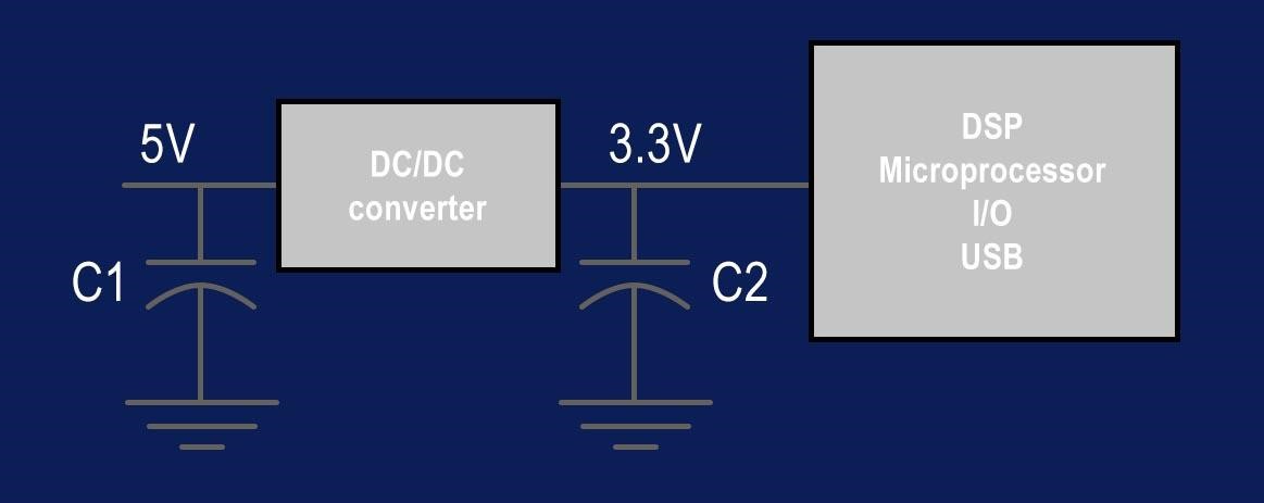
Figure 1: Simplified DC/DC converter schematic
The simplified schematic above shows what a DC/DC converter used in an automotive application to step down a +5V rail to a +3.3V rail would look like. In a DC/DC converter circuit, capacitance is required at both the input and the output of the converter. The input capacitor(s) (C1) ensures that instantaneous current is available to the converter while it is switching. The output capacitor(s) (C2) ensures that instantaneous current is available to the load (DSP, microprocessor, I/O, USB, etc) while the converter is switching. Each of these capacitors, in an automotive application, must not only be designed to meet the capacitance needs of the circuit, but also selected to meet the high temperatures and harsh conditions of the AEC-Q200 standard, and beyond.
For automotive applications utilizing the T599 series capacitors for max temperatures up to 150°C, KEMET recommends derating the voltage according to the temperature, as follows:
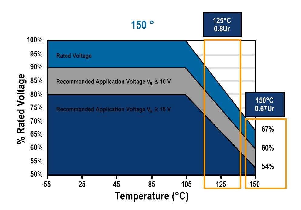
Figure 2: T599 (150ºC) Series – Temperature and Voltage Derating
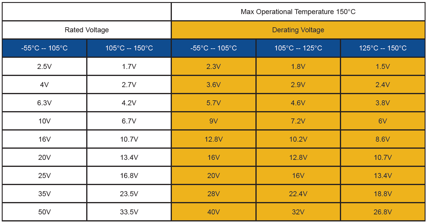
Table 1: T599 (150ºC) Series – Temperature and Voltage Derating
In the case of selecting the input capacitor (C1) for a DC/DC converter in an automotive application, the DC/DC converter needs to supply 3.3V. Let’s assume this regulator is designed for the following conditions:
VOUT = 3.3V
VIN = 5V
Efficiency (╖) = 85% (from efficiency curves in DC/DC or module datasheet)
Output transient current (ΔIOUT) = 1.0 A
Using this information, the input transient expected can be calculated as follows:
For our example, ΔIIN = (3.3/(12*.85))*1.0 = 0.78 A
Next, we must determine the series inductance. If the circuit does not include a series filter inductor, the stray inductance introduced by the PCB layout will be the only inductance. If a series filter inductor is used, that inductance value can be added to the inductance introduced by the layout.
Stray microstrip layout inductance can be calculated using the following equation:
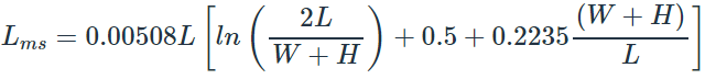
For our example, we will assume that the layout is such that the stray inductance is 50 nH, and a required filter inductor of 220 nH is used. Effective PCB layout guidelines are important because the stray inductance has a direct effect on the value of bulk capacitance required, as we will see shortly.
Next, a design decision must be made regarding how much voltage variation is permissible on the input voltage bulk capacitor. For this example, we will assume that ΔVIN(Permissible) = 0.1 V. With that, the minimum required bulk capacitance is given by the following equation:
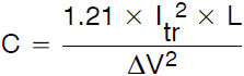
Where, Itr is the input transient current.
For our example, C = 1.21*(0.78)2*(220×10-9+50×10-9)/(0.12) = 20 µF
This is the absolute minimum bulk capacitance required. Looking at the KEMET T599 datasheet, the closest value above 20 µF with a rating above 10V (15V / 50% derating) is part number T599B336M010ATE070. This part has a capacitance of 33µF and is rated at 10V.
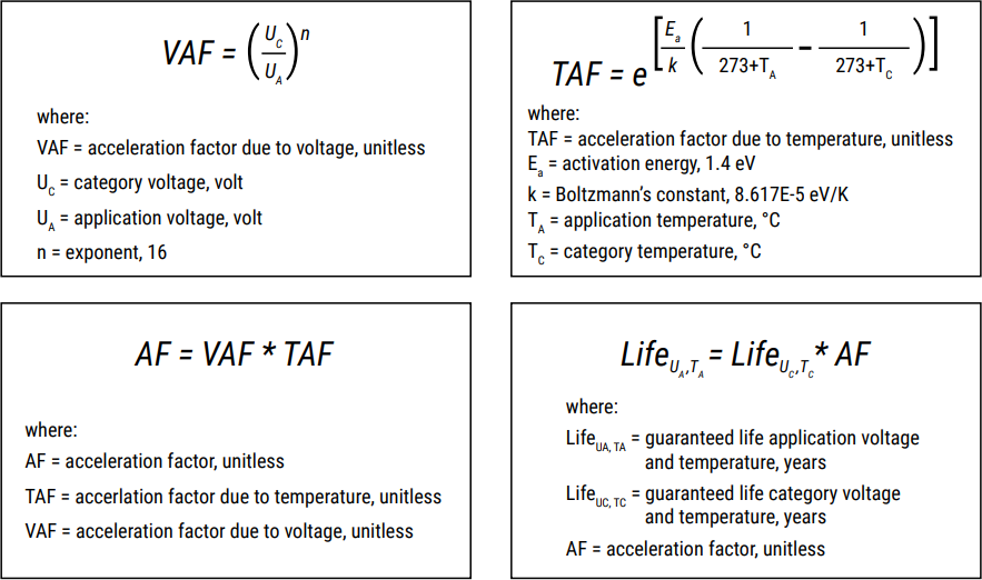
To calculate the acceleration factor due to voltage (VAF), the category voltage (UC) is the voltage rating of the capacitor, adjusted according to empirical scientific measurements performed by KEMET’s reliability team. The T599 Series with <16V rated voltage is qualified at 150ºC, 0.67xUr up to 2000h. So in our example scenario, the equation is as follows:
VAF = (10 * 0.67 / 5)16 = 108
To calculate the acceleration factor due to temperature (TAF), we will assume an application temperature (TA) of 130°C, and the category temperature (TC) is the rated temperature of the T599, 150°C.
TAF = 11
These two calculations lead us to the total acceleration factor (AF):
AF = 108 * 11 = 1,188
Finally, using the final equation to calculate the guaranteed life at the application voltage and temperature (LifeUA, TA), in years, we get the following:
LifeUA, TA = 2,000 * 1,188 = 2,376,000 hours
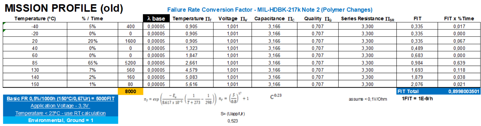
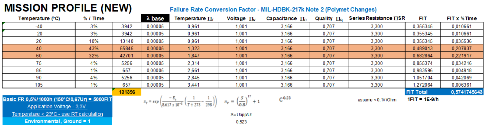
While expected life and ability to support mission profiles is important, in automotive applications it is also critically important to estimate capacitor failure rates. The common measurement in the industry is FIT, or Failures in Time, which equates to one failure per billion hours. Another way of saying this is that 1 FIT is equal to a mean time between failures (MTBF) of 1 billion hours. The reference failure rate for tantalum polymer capacitors is stipulated to be 0.5% per 1000 hours.
The total FIT for an application is the sum of the FIT at each environmental condition the design will experience, proportional to the time the design will spend at each condition. This can be represented as follows:
FIT (mission profile) = FITt1/T1 + FITt2/T2 + …+ FITtn/Tn = ∑ (FITti/Ti)
Where,
ti = time in condition I (hours)
Ti = average temperature in condition i
In each condition i, the FIT calculation is described by the equation,
λP = (λb * πT * πC * πV * πSR * πQ * πE)
Where,
λP: predicted reliability, failed parts per million part-hours
λb: established base reliability, failed parts per million part-hours
πT: temperature factor
πC: capacitance factor
πV: voltage factor (This is only applicable for polymer technologies.)
πSR: series resistance factor
πQ: quality factor
πE: environment factor
For base reliability, KEMET provides the baseline reference for tantalum polymer capacitors at λb = 0.00005.
The temperature factor, as provided by the Military Handbook (Mil-HDBK-217F- Notice 2), is provided by the following equation:
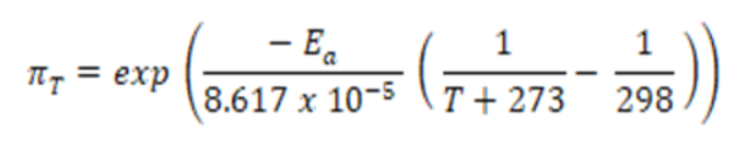
Where,
Ea = Activation Energy; 0.15eV for CWR Style Polymer technology;
T = Temperature, ˚C
The capacitance factor, as provided by the Military Handbook, is provided by the following equation:
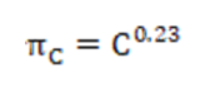
Where, C = capacitance, uF
The voltage factor, corrected from the Military Handbook, is provided by the following equation. Note that the operating voltage is the sum of applied DC voltage and peak AC voltage:
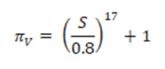
Where, S: ratio of operating voltage to rated voltage, unitless
For tantalum polymer technology, we assume <0.1 Ω/V, providing series resistance factor per the following table:
| Circuit Resistance (CR) Ω/V | πSR |
|---|---|
| >0.8 | |
| > 0.6 to 0.8 | 1.0 |
| > 0.4 to 0.6 | 1.3 |
| > 0.2 to 0.4 | 2.0 |
| > 0.1 to 0.2 | 2.7 |
| 0 to 0.1 | 3.3 |
For KEMET’s tantalum polymer technology (KO-CAP) the established failure rate is 0.5%/1,000 hours. This translates to a quality factor of SQRT(0.5) = 0.707.
For tantalum polymer technology we assume ground, benign factor.
| Environment | πE |
|---|---|
| GB (ground, benign) | 1.0 |
Putting it all together into example FIT calculations, using a 3.3 V voltage in a DC/DC circuit example, we get the results shown in the following tables. From them, we can see that we estimate a FIT of 0.9 in old legacy 8,000 hours high temperature profile, and a FIT of 0.6 in the new 130,000 hours ultra-extended mission profile.