For decades the maximum recommended operating temperature of solid electrolytic capacitors was 125°C. Responding to needs in the automotive and downhole drilling industries passive component manufacturers developed surface mount tantalum capacitors rated at 150°C in 2002-2003. Since that time the industry has introduced high temperature capable tantalum capacitors generally in 25°C increments roughly every four years. Today multiple manufacturers have products rated at 230°C poised for market release. The tantalum anode, tantalum pentoxide dielectric and manganese dioxide primary cathode material stand up well to these temperatures, although some optimization of the design and manufacturing process for these materials have been required. The primary challenges encountered when developing solid electrolytic capacitors with high temperature capabilities are associated with the carbon, silver and epoxy encapsulant materials used in conventional surface mount tantalum capacitors. Capacitor manufacturers have taken different paths to overcome these challenges. We have developed a metallized plating process to avoid issues associated with silver paints utilized in conventional Ta capacitors. We have worked with suppliers, or developed in house capabilities, to manufacture the other materials required to withstand the rigors of high temperature applications. This paper will discuss these challenges and provide reliability test data on a recently developed tantalum surface mount series capable of continuous operation at 230°C.
The primary elements of any capacitor are the positive and negative electrodes (anode and cathode respectively), and the dielectric which separates them. These basic design elements, and the materials utilized in solid electrolytic tantalum capacitors are depicted in Figure 1.
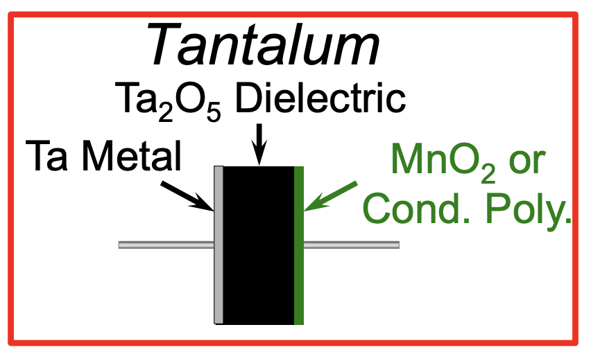
Figure 1. Tantalum, tantalum pentoxide, and a primary cathode material comprise the basic elements of a solid electrolytic tantalum capacitor.
Solid tantalum capacitors utilize a high surface area, porous tantalum pellet as the anode. These capacitors are noted for their high volumetric efficiency and reliability. The volumetric efficiency of tantalum capacitors is due in large part to the very thin, uniform amorphous tantalum pentoxide (Ta2O5) dielectric film formed on the tantalum anode via an anodic formation process. As voltage is applied to the anode in an electrolyte solution the film grows at a rate of 18 angstroms per volt. The dielectric constant of the film is 26, slightly lower than that of a COG ceramic dielectric, but due to the fact the film thickness is measured in nanometers rather than micrometers, tantalum capacitors have much higher volumetric efficiency. Another advantage of solid electrolytic tantalum capacitors compared to competing technologies is the high breakdown voltage per micron of film thickness. These properties are summarized in the table below.
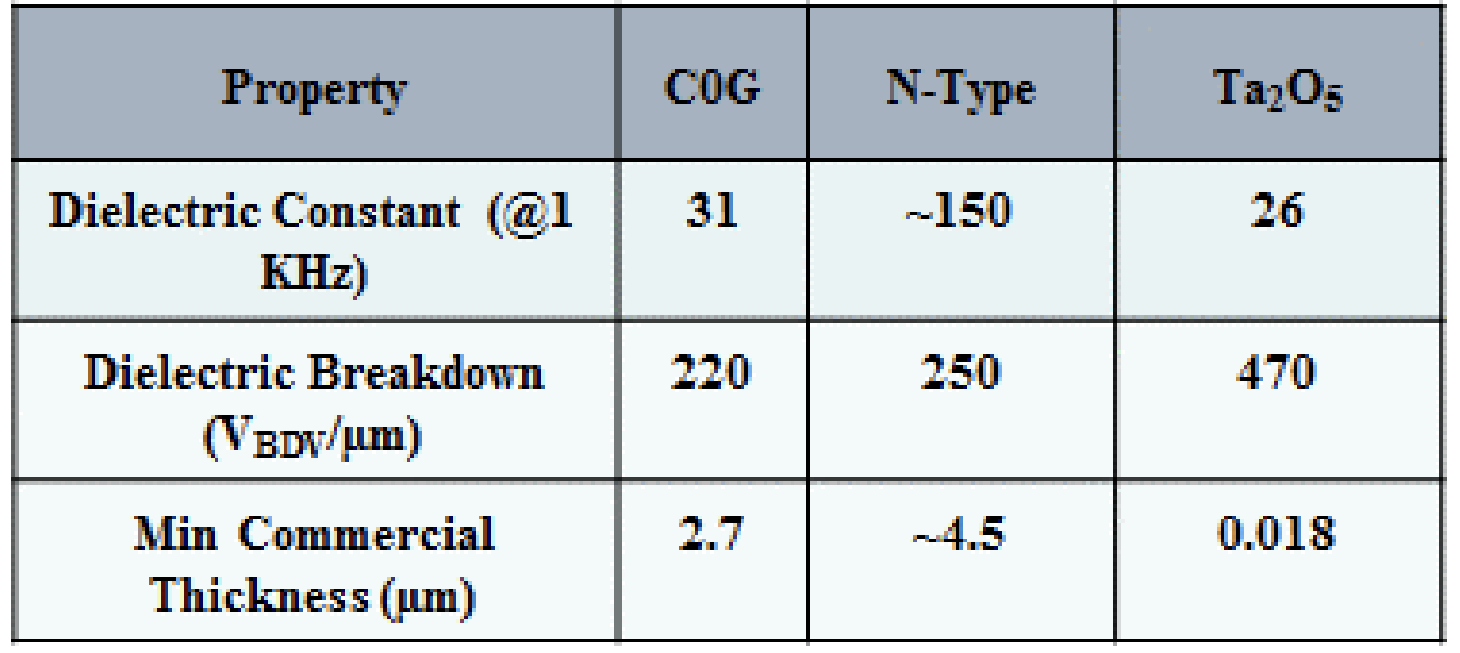
Table 1. A comparison of the key material properties of dielectrics used in high temperature applications highlight the volumetric efficiency advantages of tantalum pentoxide.
Manganese dioxide has been used as the primary cathode material for solid electrolytic capacitors since these devices were developed by Bell Labs in the early 1950’s to serve as a passive component for the newly invented transistor. Tantalum capacitors employing intrinsically conductive polymers were commercially introduced in the early 1990’s, and due to the properties of these materials, including significantly higher conductivity than MnO2, have found wide favor in recent years. However, these materials are significantly less thermally stable than manganese dioxide and will not be discussed further in this paper.
In order to reduce the ESR of the device a metallized layer covers the external MnO2 layer. Generally this metallized layer is applied by dipping the capacitor in a paint containing silver flake. Since manganese dioxide will oxidize the silver flake a carbon ink is applied to serve as a chemical barrier layer between the silver paint and MnO2 layers.
Solid tantalum capacitors are commercially available in a wide range of packaging designs, the most common and most volumetrically efficient being surface mount configurations. A common surface mount construction is depicted in Figure 2. In this design the silver coated anode is attached to a lead frame using silver adhesive. The assembled component is next transfer molded. The final assembly operations include singulating the capacitors, forming the lead frame so it wraps around the molded case and placing the capacitor in a packing material, generally tape wrapped around a reel.
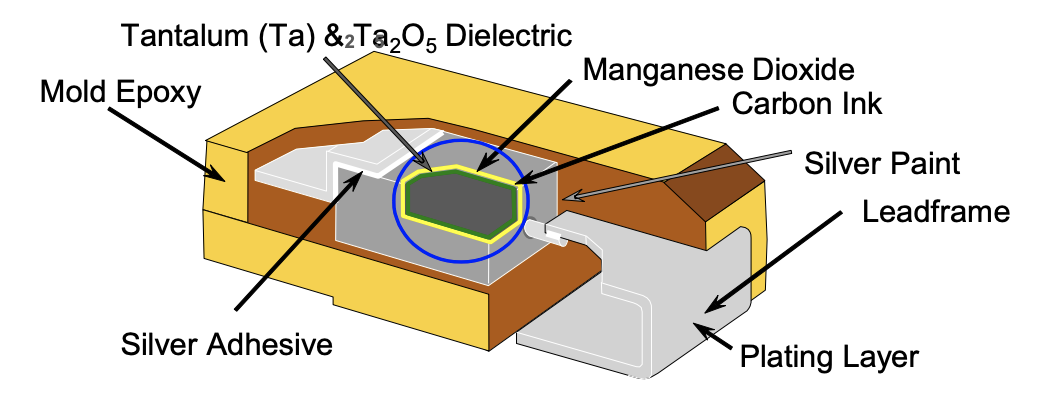
Figure 2. The general construction of a surface mount solid electrolytic capacitor showing materials which must withstand the operating temperature of the device.
Tantalum is a metal capable of withstanding very high temperatures as evidenced by a 3017°C melting point and process temperatures between 1000°C and 2000°C used to sinter tantalum powder pressed into a slug in order to form a monolithic porous anode. Tantalum pentoxide also has a high melting point of 1872°C. However, the long term reliability of tantalum capacitors, especially under high stress conditions, is undermined by two temperature and voltage accelerated failure mechanisms directly related to the thermodynamic instabilities associated with the tantalum anode and tantalum pentoxide dielectricoxygen migration from the tantalum pentoxide dielectric into the tantalum anode and crystallization of the tantalum pentoxide.
Tantalum is well known as an oxygen getter and the extraction of oxygen from tantalum pentoxide into the tantalum anode at temperatures above 200°C has been extensively studied [1, 2, 3]. It has been reported that the primary long term failure mechanism of low voltage solid tantalum capacitors is due to oxygen migration from the tantalum pentoxide dielectric into the tantalum anode [4, 5]. This migration leaves oxygen vacancies in the dielectric rendering the affected region of the dielectric more conductive, and no longer effective as a dielectric. The electric field is increased over the unaffected region, accelerating oxygen migration in this area, further concentrating the electric field over an ever thinner region of the dielectric film, ultimately leading to dielectric breakdown.
At higher voltages crystallization of the dielectric becomes an increasingly important failure mechanism [4]. In order to function properly as a high quality dielectric tantalum pentoxide must be in an amorphous state (see Figure 3). However, amorphous tantalum pentoxide is thermodynamically less stable than the crystalline form and these films slowly transition toward a crystalline state to reduce their internal energy. The instability of the amorphous form of the oxide generally increases with oxide thickness, hence higher voltage products are more prone to this failure mechanism than low voltage ones. Two factors work in the favor of engineers designing tantalum capacitors, the rate of crystallization is slow and can be further slowed by the appropriate choice of process conditions to minimize the formation of crystalline nucleation sites prior to, and during, the anodization step that forms the dielectric film.
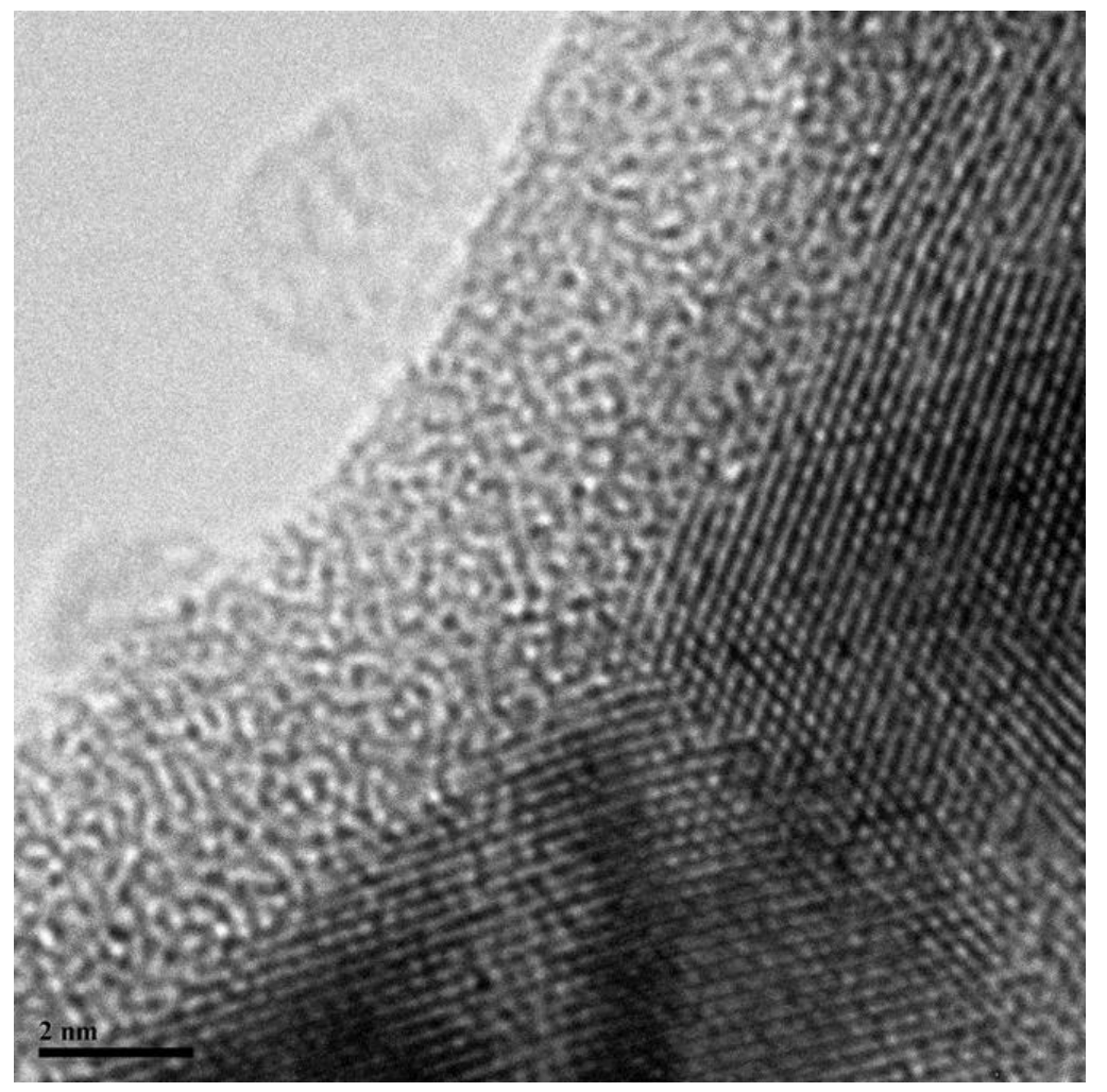
Figure 3. TEM photomicrograph of Ta/Ta2O5 showing the amorphous structure of the Ta2O5 overlying the ordered structure of the tantalum anode (previously published photo).
More recently Dr. Erik Reed has conducted a series of time to failure studies of solid electrolytic capacitors under highly accelerated temperature and voltage conditions [6, 7, 8]. Failures were determined by leakage current of a test capacitor rising to a level sufficient to blow a 1 amp fuse. Typical time to failure curves of the sort Dr. Reed used in his groundbreaking studies are depicted in Figure 3. This figure shows there are 3 primary failure regions, initial failures, a flat region where the failure rate is decreasing with time, and a wearout region where the failure rate increases dramatically. He attributes failures in the first two regions to mechanisms related to the cathodedielectric interface, while associating the wearout mechanism to changes in the tantalum metal-tantalum pentoxide dielectric interface [8]. These assertions are supported by his studies involving both MnO2 and polymer cathode systems used with tantalum capacitors. His data indicate that the initial failures and failures in the flat region are highly accelerated by voltage, but only moderately impacted by temperature. Failures in the wearout region are highly accelerated by both temperature and voltage. Since we are primarily concerned with failures modes which are accelerated by temperature, we will restrict our discussion to the wearout region of the time to failure curves.
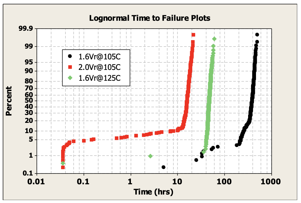
Figure 4. Time to failure curves for solid electrolytic tantalum capacitors under highly accelerated test conditions clearly show that voltage and temperature accelerate the time to ‘wearout’
Although the primary purpose of Dr. Reed’s work was to develop empirical reliability models for the capacitors tested, his papers provide intriguing insights into the physics behind the failures in the various regions of the time to failure curves. The author used a simple power law equation to model voltage accelerated time to failure and an Arrehenius model for the temperature accelerated time to failure. His data indicated an interaction between the temperature and voltage induced acceleration as evidenced by a decrease in the activation energy used in Arrhenius model as the test voltage increased. Likewise he observed that the empirically derived exponent in the power law model for voltage acceleration decreased as the temperature increased.
Dr. Yuri Freeman suggested a physics based model to correlate the time to failure data [5]. Dr. Freeman’s model was based on the temperature and voltage induced migration of oxygen from the tantalum pentoxide dielectric into the tantalum. Based on work Dr. Freeman had conducted years earlier he suggested the constants for this physics based model. The model suggested by Dr. Freeman fit Dr. Reed’s data quite well, except at lower test voltages. To account for this deviation Dr. Reed introduced a 2nd term in the model. He proposed this second term was needed to account for the second well known failure mechanism associated with the tantalum pentoxide dielectric- field driven crystallization.
In order to slow down the two dominant failure mechanisms associated with the thermodynamic instability of the tantalum pentoxide and the tantalum-tantalum pentoxide interface high temperature capable solid electrolytic capacitors are designed with low specific surface area powders and processed using high formation to rated voltages ratios and ‘clean’ process technologies [9].
Manganese oxide is one of the most thermally stable components used to manufacture solid electrolytic tantalum capacitors as evidenced by Figure 5, a TGA curve for this material. In order to ensure the robustness of the finished capacitor, the process for application of the manganese dioxide layer was optimized to ensure a dense, uniform external coat protecting the anode from thermo-mechanical stresses associated with high melting point (HMP) solder reflow conditions and shock and vibration conditions common in downhole drilling.
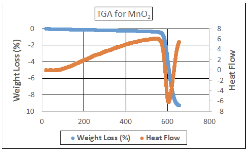
Figure 5. TGA for MnO2 powder indicates the material is stable up to about 580ºC where conversion to non-conductive Mn2O3 occurs.
The external manganese oxide layer is coated with a carbon ink layer and a metal filled layer. The conductive materials in these two layers, generally graphite flake for the carbon ink and silver flake for the metal layer, can withstand temperatures in excess of 300ºC without significant degradation. However, the binders used in many commercially available carbon ink and silver paint formulations begin to degrade at temperatures of 200ºC or below. The degradation of the binder system leads to an excessive increase in equivalent series resistance (ESR) of the capacitor, thus rendering these formulations unsuitable for use in a capacitor rated for continuous operation at temperatures above the onset of thermally induced degradation. Figure 6 and 7 depict TGA‘s from cured films of a conventional carbon ink and silver paint, respectively.
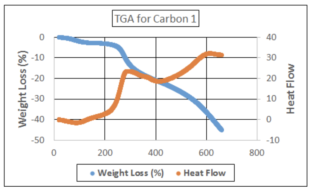
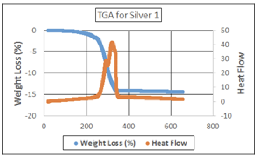
Figures 6 and 7. In contrast to the TGA for MnO2, the TGA for a carbon ink and silver paint frequently used for capacitors manufactured for consumer applications exhibit significant degradation in the temperature range of interest to the downhole drilling industry.
In order to develop capacitors capable of withstanding continuous operation at temperatures of 200°C and above, carbon and silver formulations based on more thermally robust binders were developed. The TGA curves for one such carbon and silver are depicted in Figures 8 and 9.
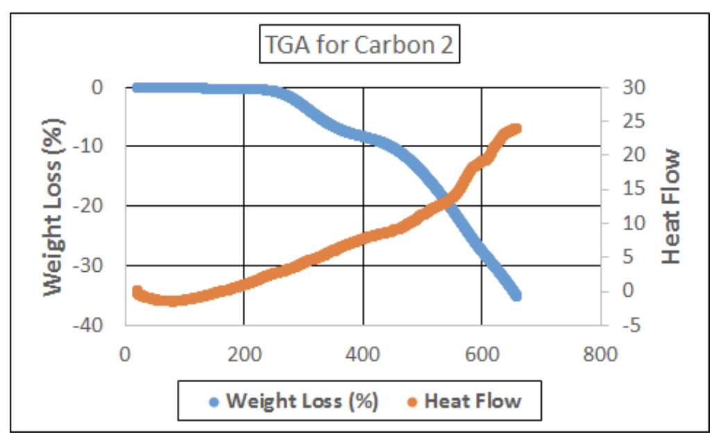
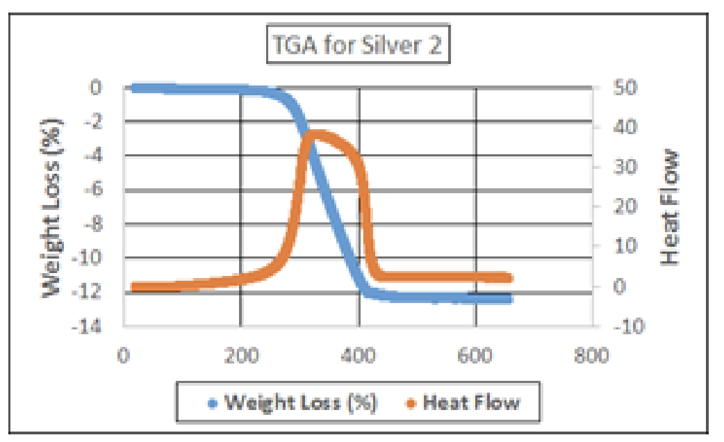
Figures 8 and 9. The TGA of carbon and silver formulations developed for solid electrolytic tantalum capacitors rated for continuous operation at temperatures of 200ºC and above.
The use of carbon and silver formulations developed for high temperature applications resulted in ESR for unencapsulated capacitors that was stable at temperatures in excess of 200°C for 1000 hours or more.
Although the ESR of the unencapsulated capacitors was stable, it was soon discovered that leakage was not. Initially investigators suspected the usual suspects associated for high temperature induced leakage failures, oxygen migration and crystallization of the dielectric. Considerable effort was devoted to improving the dielectric and suppressing these failure mechanisms, with minimal improvement in the observed performance at high temperatures. Ultimately a series of tests were run where the capacitors were exposed to a high temperature storage life test after each of the cathode layers were applied. It was found that the leakage was stable at each point in the process prior to the application of the silver paint. Although silver migration was a known failure mechanism for solid electrolytic capacitors in humid environments, to our knowledge it had not been observed in the very dry environments of a 200°C life test. In order to eliminate silver migration as potential cause of high temperature leakage failures, the silver layer was replaced by a nickel layer applied via a patented electrochemical plating process [10]. The results provide further strong evidence that silver migration is a potential cause of leakage failures in solid electrolytic capacitors during very high temperature unbiased life tests. The use of an electroplated metal layer provides other advantages to the reliability of a capacitor in a high temperature environment. It eliminates the polymer used in the traditional metal filled layer and provides a hard shell around the anode to protect it from thermal and mechanical shocks. The value of this is not to be underestimated for a dielectric with a thickness measured in nanometers! The use of a metal plated layer to provide stable leakage performance at elevated temperature in a solid electrolytic capacitor is covered in a pending patent application [11].
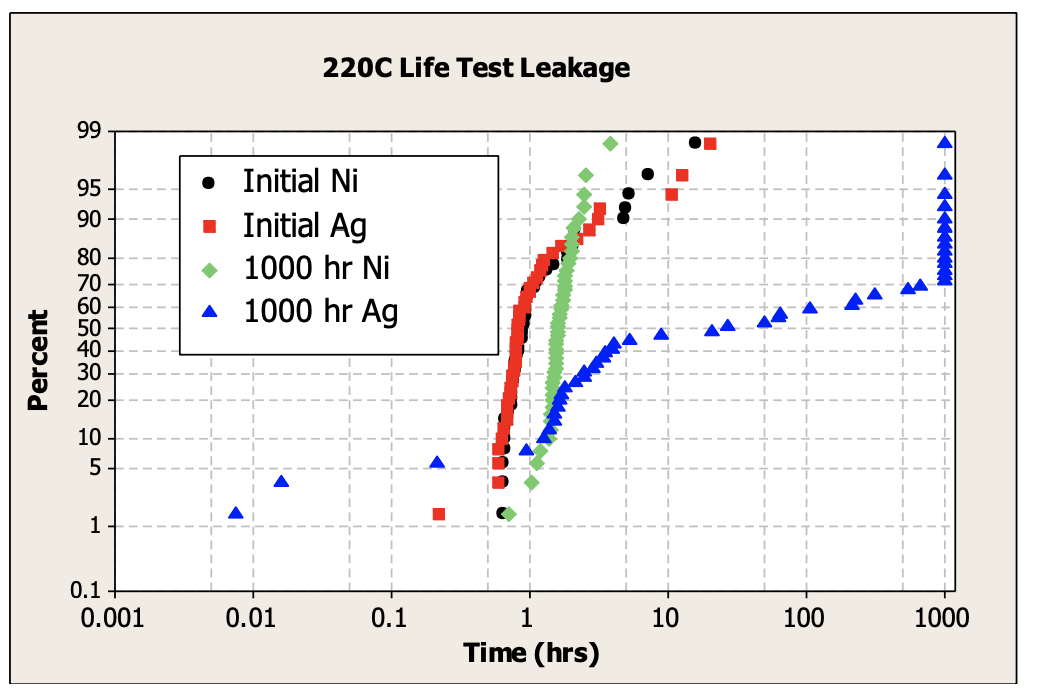
Figure 10. Ta capacitors designed with a silver paint layer are shorts after 1000 hours at 220ºC, while parts manufactured with an electroplated Ni layer exhibit stable leakage.
Having encountered silver migration from the silver paint layer during elevated temperature life testing, researchers were not surprised to observe a muted form of it arising from the use of a silver adhesive to attach the metal plated component to the leadframe. In this case the failure mechanism was eliminated from the design by replacing the silver adhesive with a transient liquid phase sintering (TLPS) adhesive. These materials have the unique property of melting at temperatures suitable for construction of electronic components, but once cured the metals form alloys with much higher melting points, another strong advantage for a very high temperature application. The use of this class of adhesives to form a metallurgical bond between the leadframe and a plated metal layer which encompasses the capacitor provides for a mechanical strength unattainable with conventional organic based paints and adhesives. The use of TLPS adhesives in conjunction with a plated metal layer in solid electrolytic capacitors is patent protected [12].
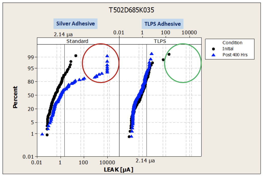
Figure 11. Silver migration from the silver adhesive is eliminated using a transient liquid phase sintering adhesive.
The final material set used to manufacture most surface mount solid tantalum capacitors is the molded case. As described above, tests conducted during the early stages of the development of high temperature capacitors showed that optimization of the cathode layers which contained organic materials had to be modified to withstand the rigors of long term exposure to temperatures above 200°C. Following the replacement of the organic component in conventional carbon formulations with a material better capable of withstanding high temperatures without degradation, and elimination of the organic components in the metallized layer and the adhesive used to bond components to the lead frame, unencapsulated components were shown to exhibit stable ESR during high temperature life tests. However, after the components were encapsulated during a transfer molding process, significant ESR increases were once again encountered during 215° and 230°C life tests. Failure analysis indicated there were separations between the external cathode layers. Once again the development team had to modify a key material set in order to design a solid electrolytic capacitor capable of surviving in extreme temperature environments. Numerous epoxy formulations were investigated, and although many showed improvements relative to conventional materials used for surface mount capacitors, the performance of one formulation tested was clearly superior to the others. Figure 12 shows that layer separations were prevented using the new molding compound.
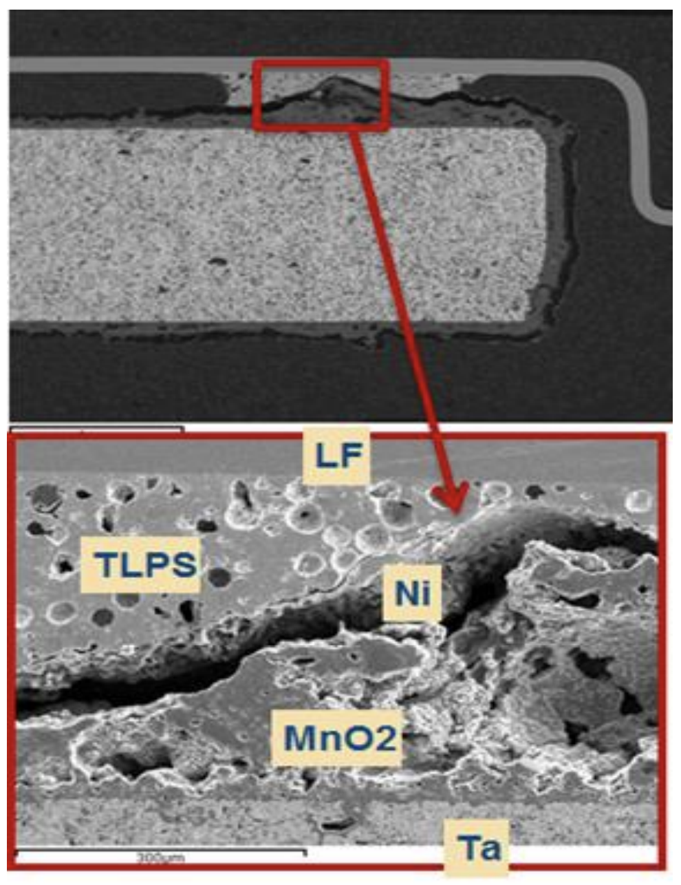
Figure 12. Separation between the cathode layers caused high ESR during high temperature life testing of tantalum capacitors.
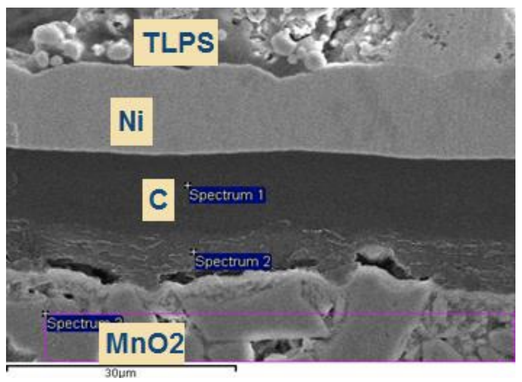
Figure 13. Optimization of the molding compound used to encapsulate the capacitors eliminated the separations between cathode layers resulting in stable ESR during life test.
The first step in any reliability assessment of solid electrolytic capacitors is to solder the components to a board. In order to test conventional capacitors the components are typically mounted to a board using either a Sn-Pb or Pb-free solder paste. In order to avoid reflow during use conditions capacitors rated for >200°C environments need to be mounted using a high melting point solder (HMP solder) with a melting point of 300°C or higher. The component can be mounted using a soldering iron, a reflow oven or a solder wave, each of which subjects the capacitor to very high process temperatures which can lead to stresses due to the CTE mismatches in the construction of the component. These thermo-mechanical stresses are far greater than those conventional capacitors are exposed to during the mounting process, increasing the possibility the parts might fail before even being exposed to the elevated operating temperatures for which they were designed.
To date we have mounted thousands of capacitors to specially designed high temperature boards using an HMP solder (composition is 93.5%Pb, 5% Sn, 1.5% Ag; solidus temperature 275°C; liquidus temperature 302°C) with both a soldering iron and a convection reflow oven without a single post board mount failure. The reflow profile used in mounting is shown in Figure 14 below.
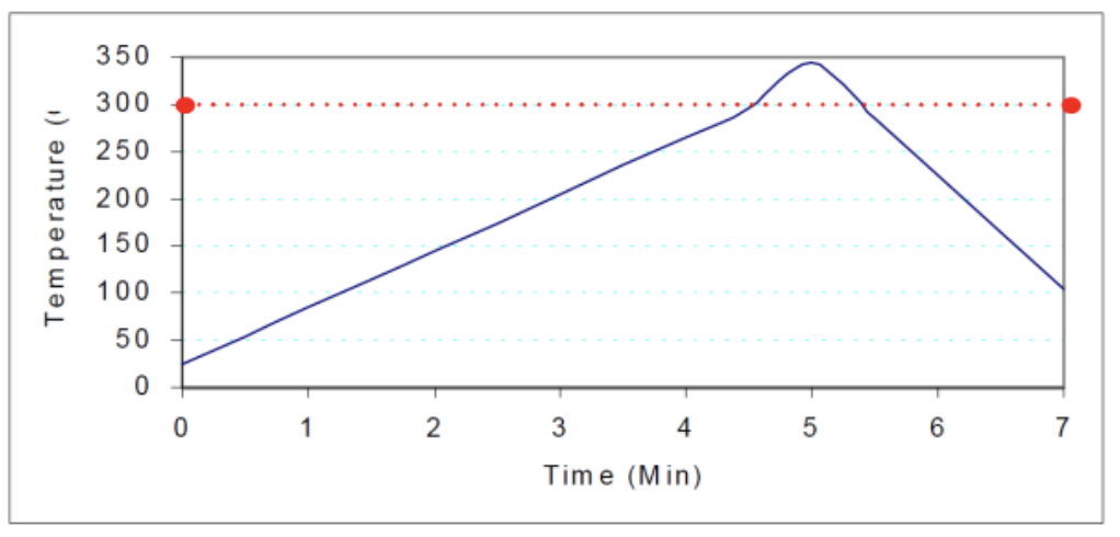
Figure 14. Recommended reflow profile for HMP solder
Once components were mounted to the board we measured the capacitance change as a function of temperature. We observed a roughly 22% increase in capacitance between room temperature and 230°C.
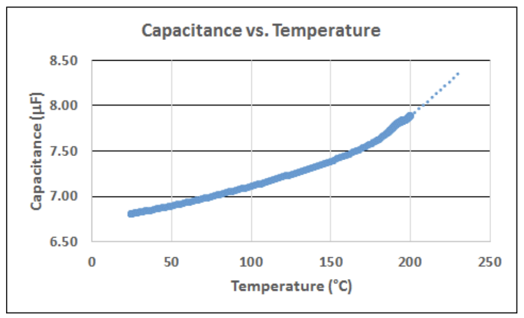
Figure 15. Capacitance of a solid tantalum capacitor rises approximately 22% between 25º and 230ºC.
The voltage derating at elevated operating temperatures was determined by extrapolating from common deratings at lower temperatures. For 230ºC application, the derating was determined to be 80%.
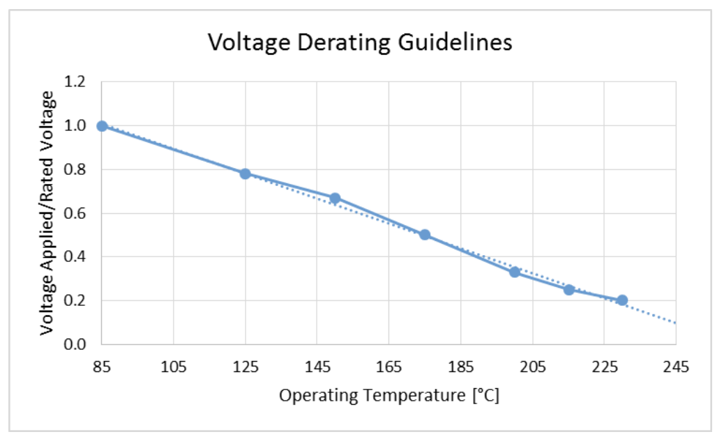
Figure 16. The derating for a tantalum capacitor was calculated by extrapolating traditional derating rules applied at lower temperatures.
Next, life test was conducted on mounted capacitors at 230ºC with 80% derating for a duration of 500 hours. Apart from an initial shift in ESR which steadies in subsequent measurements, all measured parameters are stable. Results from 35Vr 7343 footprint, 16Vr 3528 footprint, and 35Vr 6032 footprint capacitors are shown below. Endurance testing is scheduled for 1,000 hours and longer as test capacity allows, but data is not yet available at the time of publication.
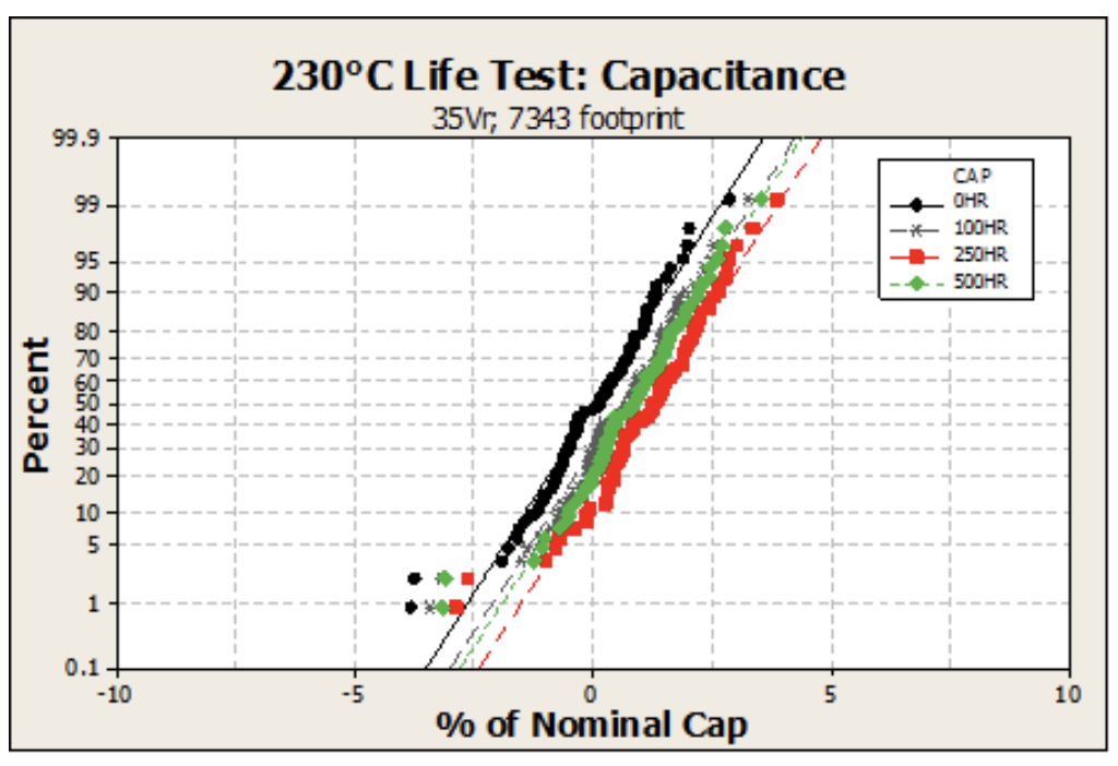
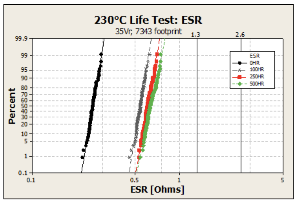
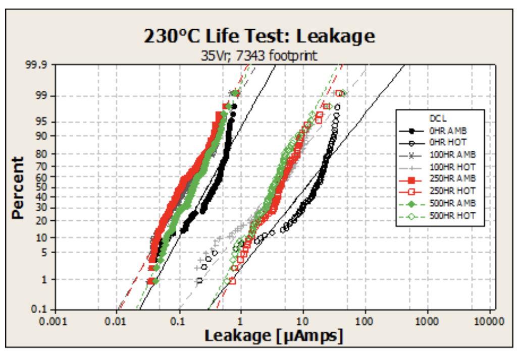
Figures 17, 18, 19. The capacitance, ESR and leakage of 35V rated, 7343 footprint solid tantalum capacitors are stable through 500 hours of life test at 230ºC.
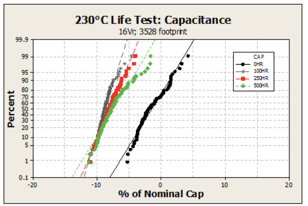
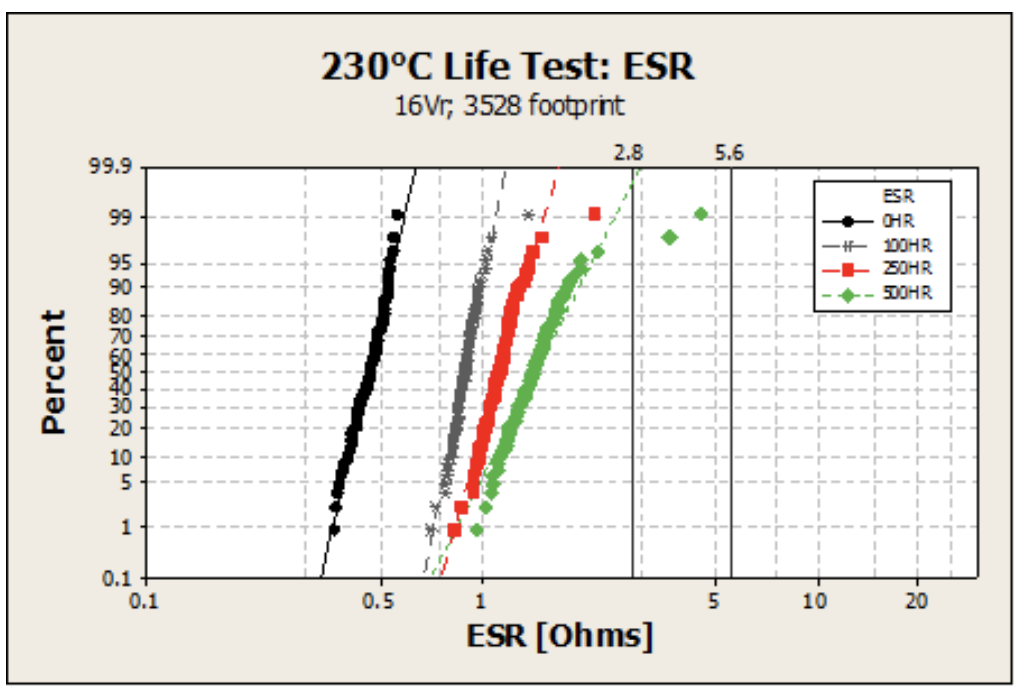
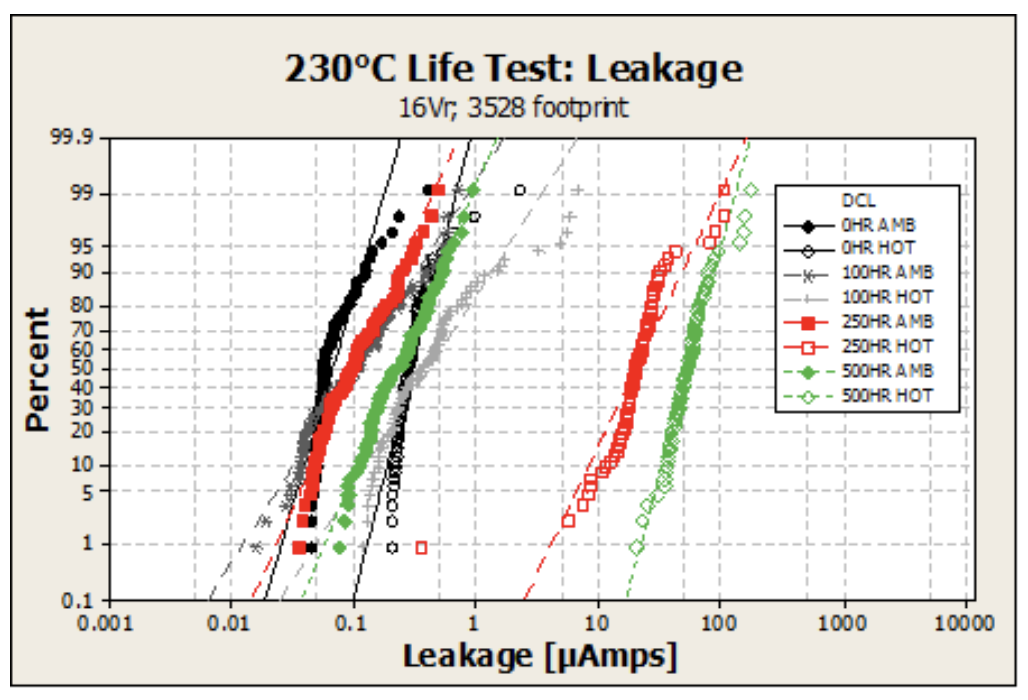
Figures 20, 21, 22. The capacitance, ESR and leakage of 16V rated, 3528 footprint solid tantalum capacitors are stable through 500 hours of life test at 230ºC.
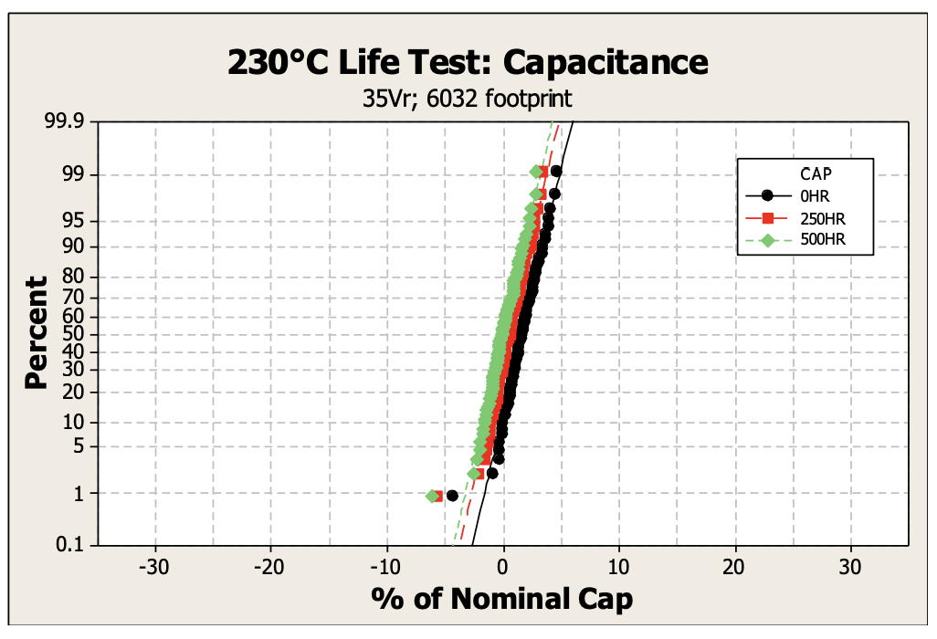
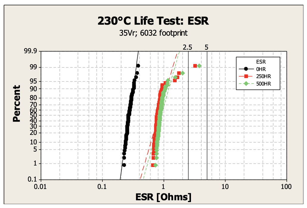
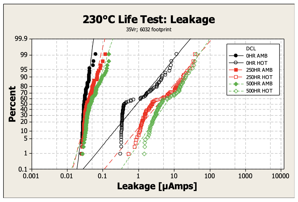
Figures 23, 24, 25. The capacitance, ESR and leakage of 35V rated, 6032 footprint solid tantalum capacitors are stable through 500 hours of life test at 230ºC.
Thermal Shock testing was completed through 1000 cycles at temperatures of -55ºC to +125ºC (15 min minimum dwell, 1 min maximum transfer time). Extremely stable performance was observed.
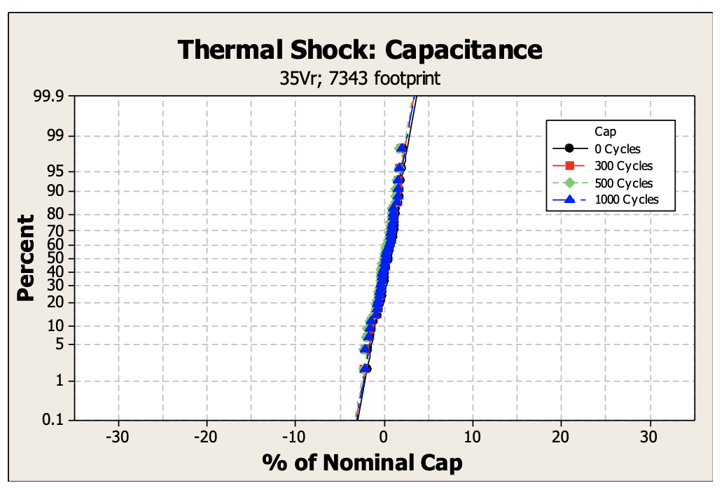
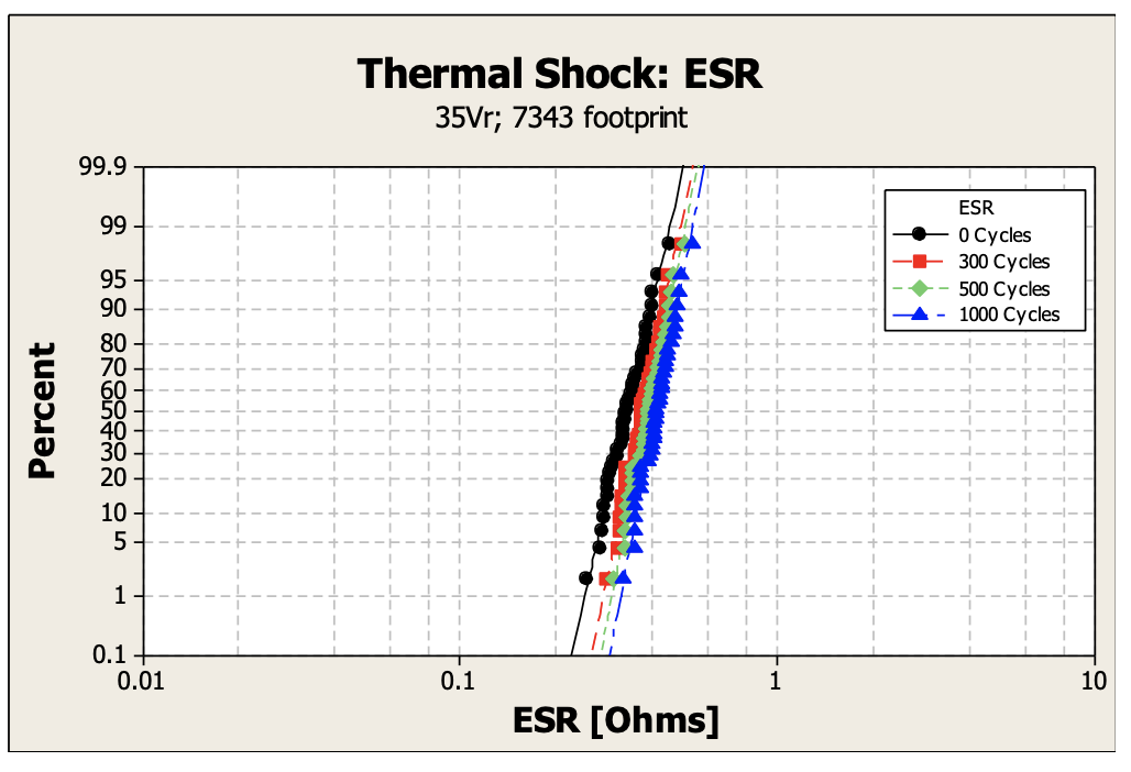
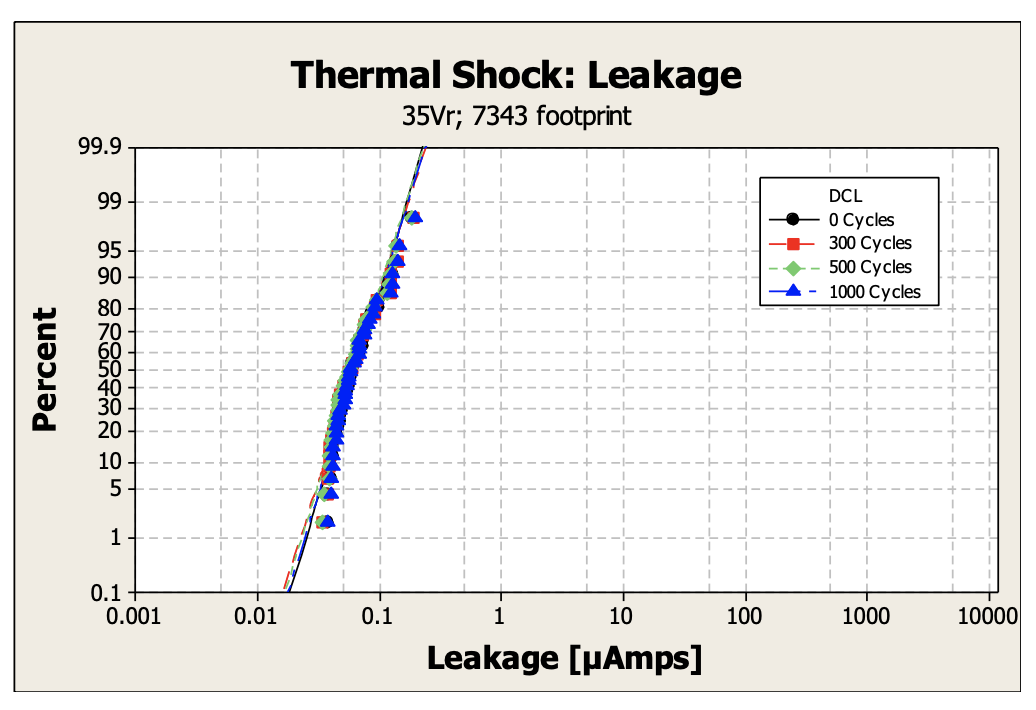
Figures 26, 27, 28. The capacitance, ESR and leakage of 35V rated solid tantalum capacitors are stable through 1,000 cycles of Thermal Shock.
Capacitance, impedance, and ESR were measured over frequency ranging from 100 to 10 million Hertz as shown in Figures 29 and 30 below.
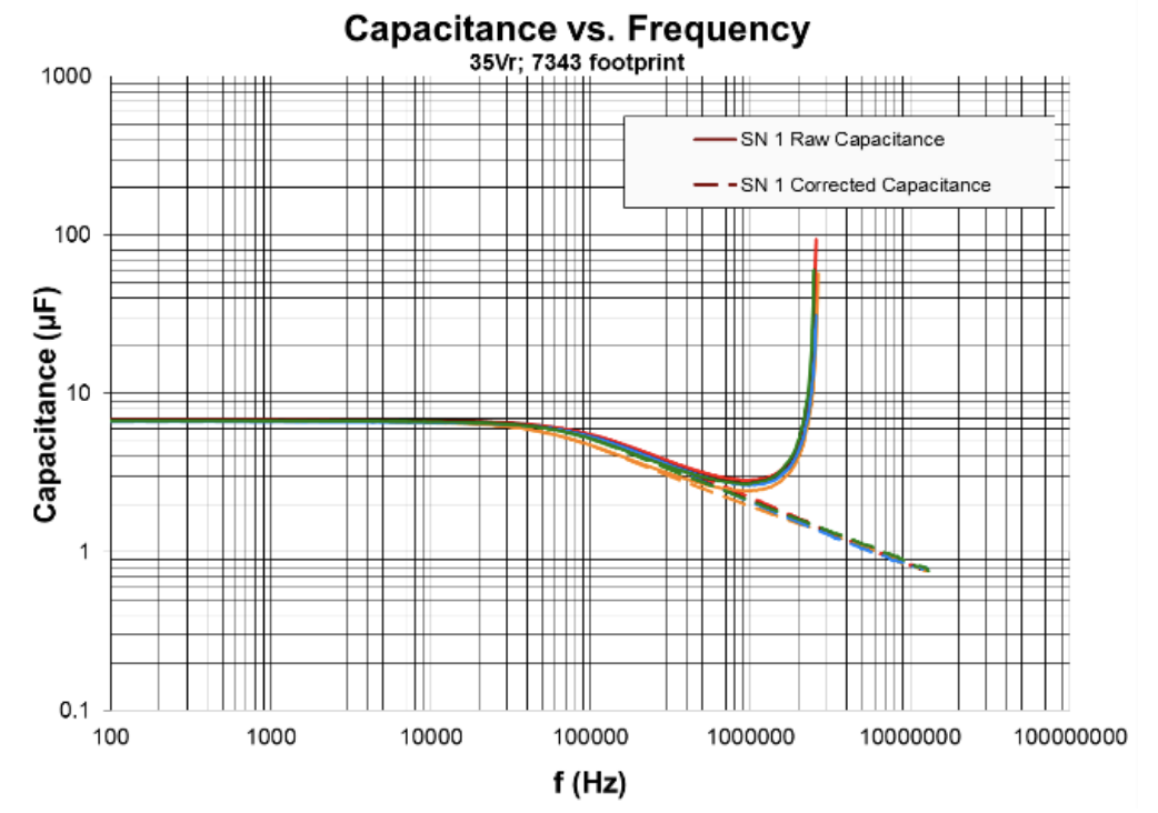
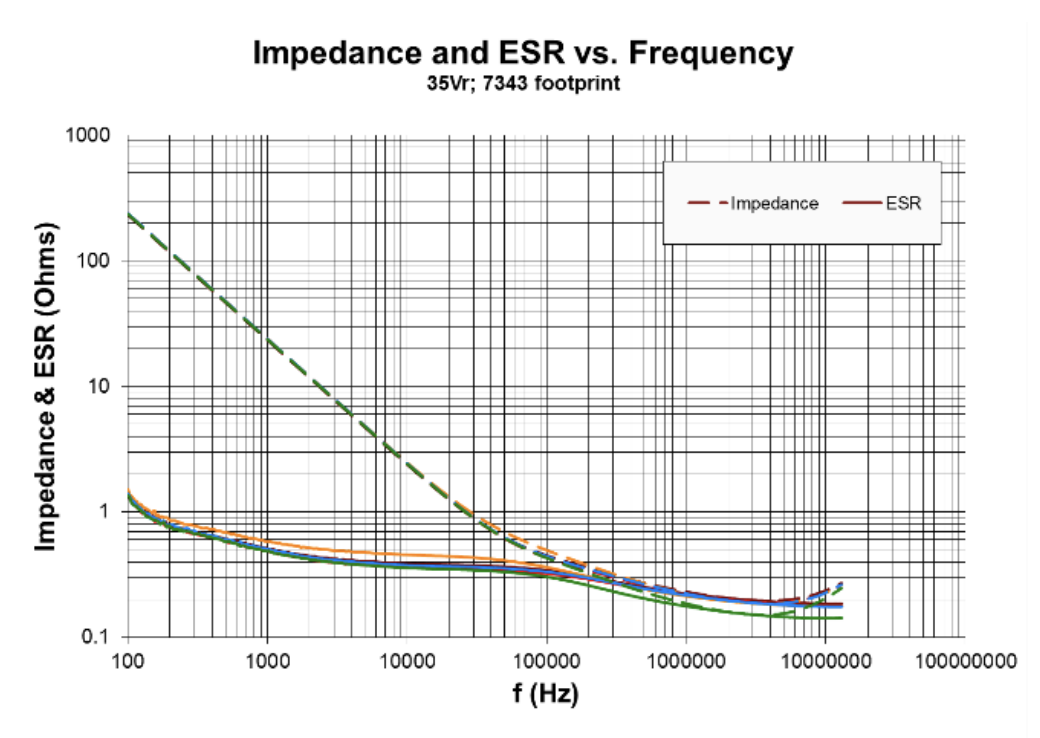
Figures 29, 30. Capacitance vs Frequency and Impedance/ESR vs Frequency of 35V rated solid tantalum capacitors.
While the calculated derating at 230ºC was determined to be 80% based on extrapolating from common deratings at lower temperatures, the stable leakage behavior of the parts during 230ºC endurance testing indicated that the part capability could potentially exceeded this derating. Time to failure testing at 230ºC was conducted at several voltages to assess both the reliability of the part as well as the derating. At 0.4Vr, no failures (leakage current not sufficienly high to blow a 1 amp fuse) were recorded after 600 hours on test. Two failures occurred at 0.5Vr during the 600 hour test. The time to failure plot for 1.0Vr and 0.8Vr is shown in Figure 31 below with 50 percent of the population failing at approximately 15 and 150 hours respectively.
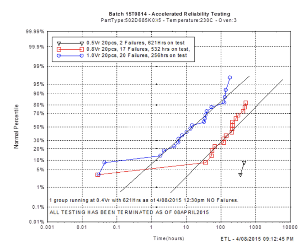
Figures 31. Time to failure testing at 230ºC for 35V rated solid tantalum capacitor indicates potential for lower derating at application temperature.
The results presented in this paper demonstrate the importance of external coating, adhesive, and epoxy encapsulant materials in high-temperature applications exceeding 200ºC common to downhole and automotive applications. Through development (in house and via suppliers) of carbon coatings, a metalized plating process, TLPS adhesive, and plastic mold compound able to withstand endurance testing at 230ºC, we have shown stable performance results on tantalum surface mount capacitors. Additionally, the challenges of mounting the parts utilizing high melting point solder in a reflow oven exceeding 300ºC was demonstrated with no initial failures on thousands of mounted parts. The results of time to failure testing indicates that derating rules extrapolated from lower temperature applications may be too aggressive for applications exceeding 200ºC, and work is in progress on further evaluating product capability at lower deratings.
While the authors are solely responsible for the content of this paper, we gratefully acknowledge the technical insights and guidance of Dr. Yuri Freeman through the course of this project.