While carbon-neutral efforts are accelerating worldwide, the growth rate of BEVs and PHEVs in the automotive market is also accelerating rapidly. In 2020, EVs made up 3% of global sales. Some official publications estimate that it will grow to be 15% by 2025, 39% by 2030, and 66% by 2035.
As a result, the use of electrical components in automotive applications is increasing, which has caused the scope of applications in ECE R10 (the UN regulation on EMC first issued in 2011) to expand. Therefore, EMC measures for automotive products have become a must.
KEMET SCF-XV, SCR-XV and SCT-XV series offer a standard line-up of 321 part numbers of common mode choke coils (CMC) fully qualified to the automotive AEC-Q200 standard, effective for EMC countermeasures for automotive products. In this article, we will introduce the primary performance and selection criteria for common mode choke coils.
Magnetic flux:
Through a coil, magnetic flux is generated when current flows through a magnetic core.
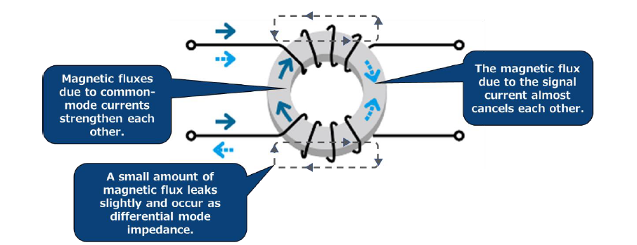
Figure 1
The common-mode choke coil has two wires wound so that the fluxes of the signal currents cancel each other, and the common-mode currents strengthen each other’s fluxes. The advantage of common-mode coils is that they eliminate common-mode noise without affecting the power and signal lines. In addition, the leakage flux generated by the component also serves to eliminate differential mode noise. The performance of a common mode choke coil depends mainly on the magnetic material. The higher the impedance at the required frequency point, the more effective the noise suppression. The Curie temperature (Tc) should also be checked along with the operating environment.
Theoretical formula for inductance and performance of magnetic materials:
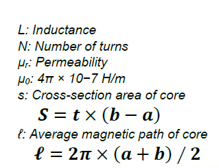
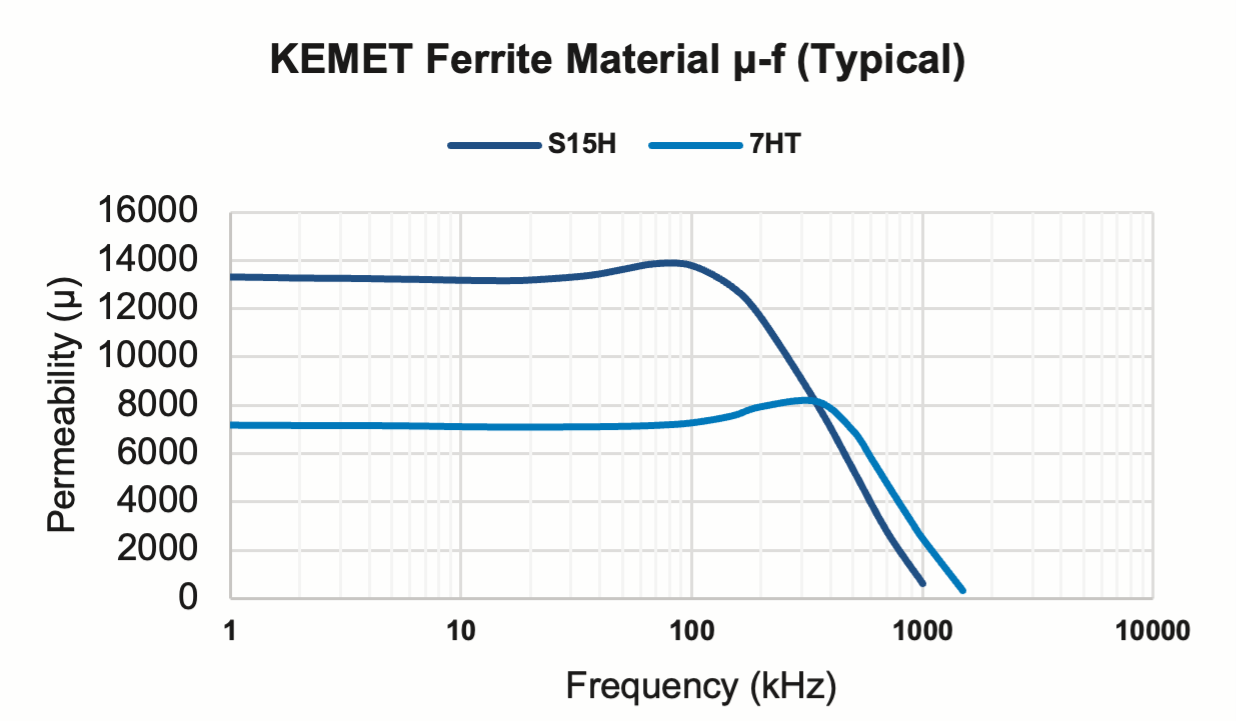
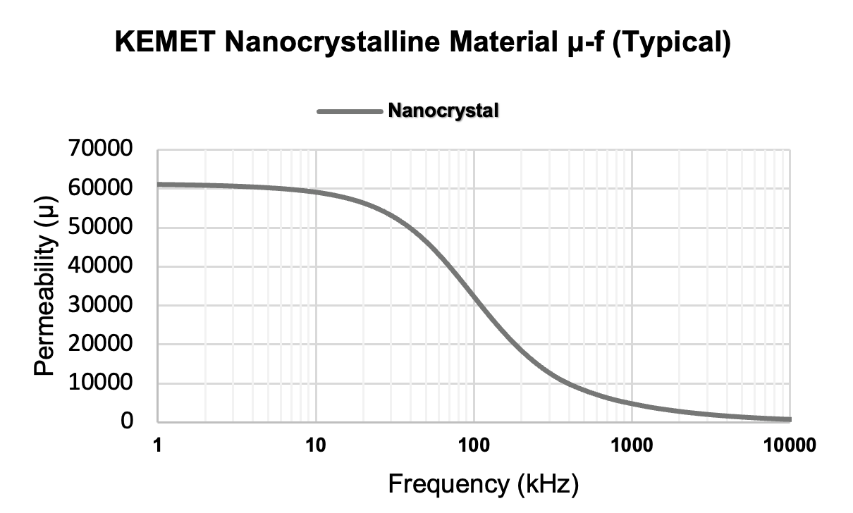
The theoretical formula for the inductance of a toroidal core can be seen below (Figure 2). Based on this formula, the larger the permeability, the higher the inductance (Figure 3). However, the higher the magnetic permeability, the quicker the material saturates, so selecting the core material according to the frequency band for noise suppression as desired is critical.


Figure 2
Temperature characteristics of magnetic materials:
Temperature characteristics are also important in the selection of common mode choke coils. Figure 4 shows the relationship between magnetic permeability and temperature.
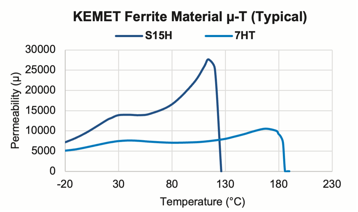
Figure 4 – Permeability vs. Temperature
Around the point where the magnetic permeability drops is the heat resistance temperature of the core, called the Tc. The KEMET SCR-XV series uses high permeability S15H material (Tc >120°C) for high inductance, and the SCT-XV series uses 7HT material (Tc >180°C) for high heat resistance, allowing selection according to the application. Furthermore, the Curie temperature of the nanocrystal core is over 500°C, which is higher than that of ferrite.
These SCR-XV and SCT-XV series use high CTI performance plastics for the insulation case to ensure a 5mm insulation distance. As a result, it achieves the industry’s highest-rated voltage of 1,000 V and can be used for higher voltage applications in BEV and PHEV systems.
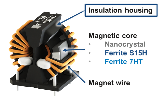
Figure 5
Creepage distance to avoid failure due to tracking based on IEC60664-1:
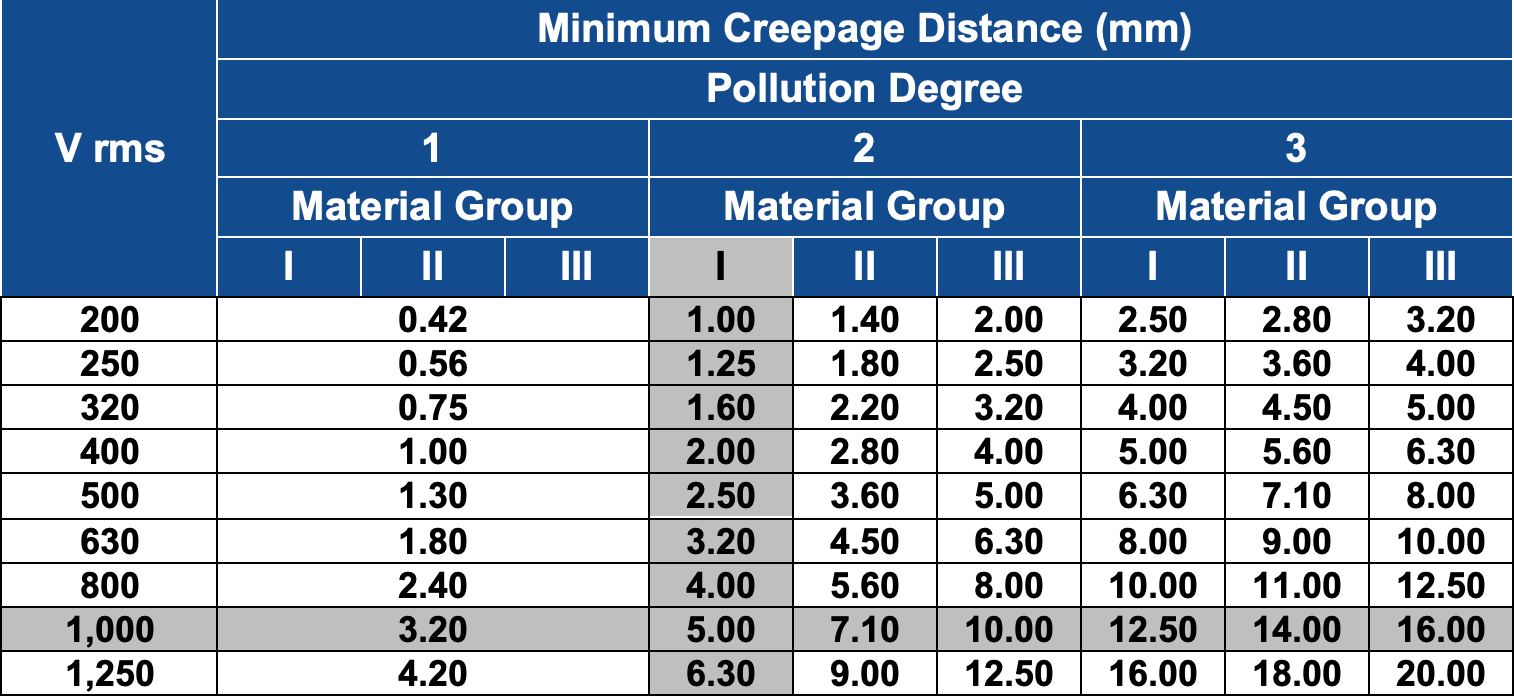
Table 1
Pollution degree: 2
Only non-conductive pollution occurs, except that occasionally a temporary conductivity caused by condensation is to be expected.
Material group: Ⅰ
600 ≤ CTI (Comparative Tracking Index)
Creepage distance:
5.00 mm at 1,000 V
EMI filters consist of a choke coil and a capacitor. In many cases, multiple combinations of common mode choke coils and capacitors are used. It is important to combine them in an appropriate configuration according to the EMI countermeasure frequency point. This section will introduce how attenuation performance varies based on how the common choke coil and capacitor are combined.
EMI filter basic structure and role of elements:
The EMI filter configuration in Figure 6 is a second-order configuration for both common mode and differential mode attenuation using a common mode choke and X, and Y rated safety capacitors. KEMET products were used to simulate this configuration, and the resulting attenuation characteristics can be seen in Figures 7 and 8.
Element Values:
CMC: SCR25XV-150-1R6A010JV (15 A, 1 mH)
Cx: R475N3330CK01M (0.33 µF)
Cy: P295BE471M500C (470 pF)
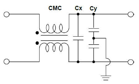
Figure 6
– Common mode attenuation: CMC(Lc)-Cy
– Differential mode attenuation: CMC(Ln*)-Cx
* Ln = Leakage inductance
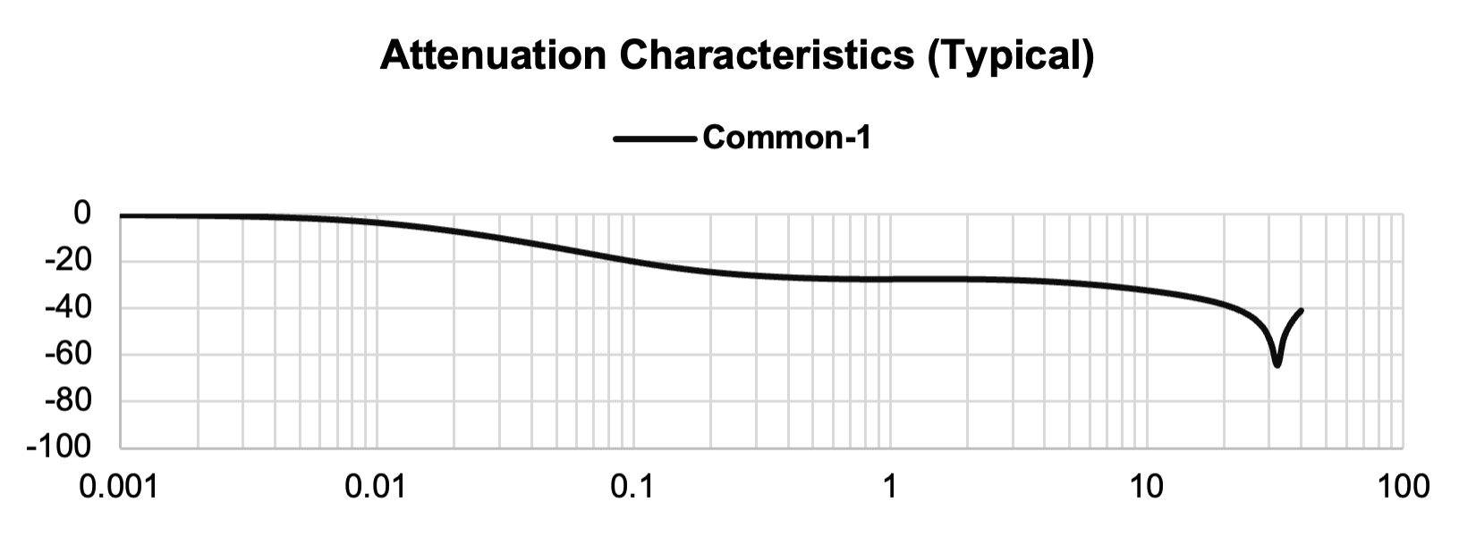
Figure 7
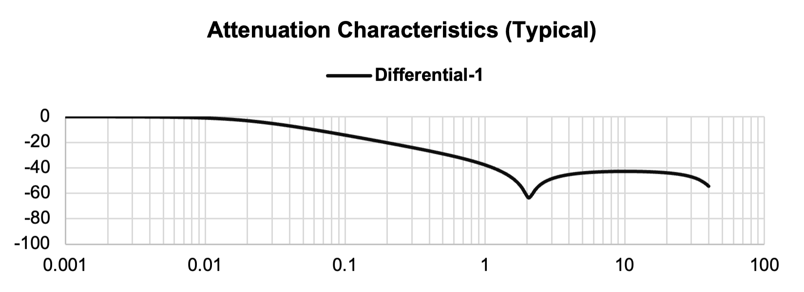
Figure 8
Next, let’s look at the difference in attenuation performance based on the position of the capacitors when two common mode choke coils are used. An additional common mode choke is introduced to the circuit, and the configuration seen in Figure 9 is simulated. Attenuation characteristics can be seen in Figures 10 and 11. Configuration with two common mode chokes – 1: CMC1-CMC2-Cx & Cy:
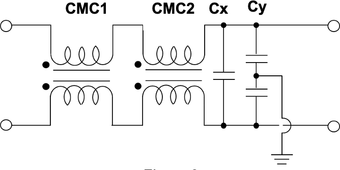
Figure 9
Common mode attenuation: CMC1(Lc)-CMC2(Lc)-Cy
Differential mode attenuation: CMC1(Ln)-CMC2(Ln)-Cx
Element Values:
CMC1: SCR25XV-150-1R6A010JV (15 A, 1 mH)
CMC2: SCR25XV-150-1R6A010JV (15 A, 1 mH)
Cx: R475N3330CK01M (0.33 µF)
Cy: P295BE471M500C (470 pF)
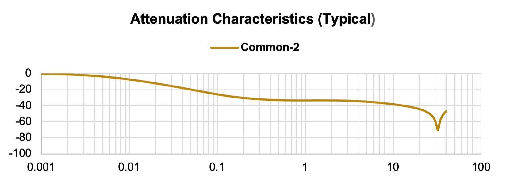
Figure 10
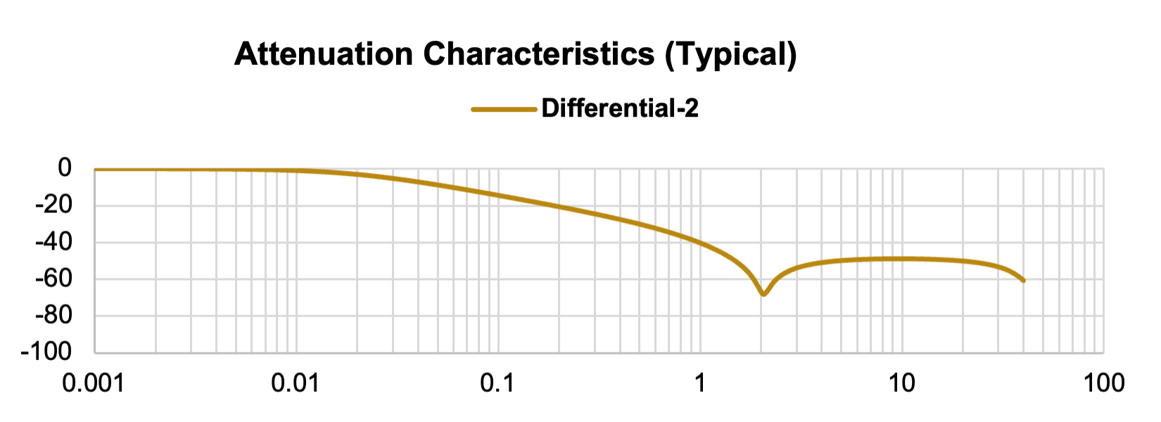
Figure 11
The attenuation performance improves due to the increase in CMC components, which is slightly effective. However, this is still a second-order noise filter configuration.
The filter circuit is then rearranged, and the configuration seen in Figure 12 is simulated. Configuration with two common mode chokes-2: CMC1-Cx & Cy-CMC2:
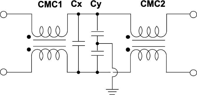
Figure 12
Common mode attenuation: CMC1(Lc)-Cy-CMC2(Lc)
Differential mode attenuation: CMC1(Ln)-Cx-CMC2(Ln)
Element Values:
CMC1: SCR25XV-150-1R6A010JV (15 A, 1.23 mH)
Cx: R475N3330CK01M (0.33 µF)
Cy: P295BE471M500C (470 pF)
CMC2: SCR25XV-150-1R6A010JV (15 A, 1.23 mH)
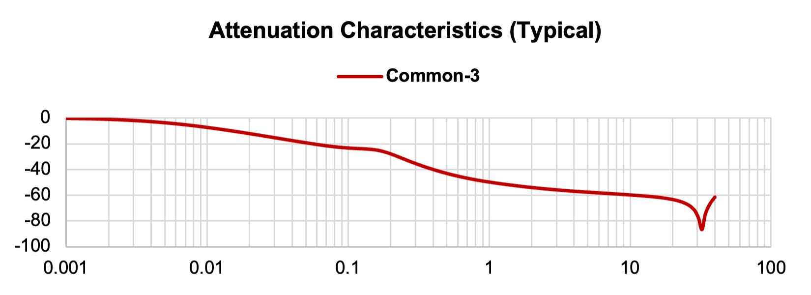
Figure 13
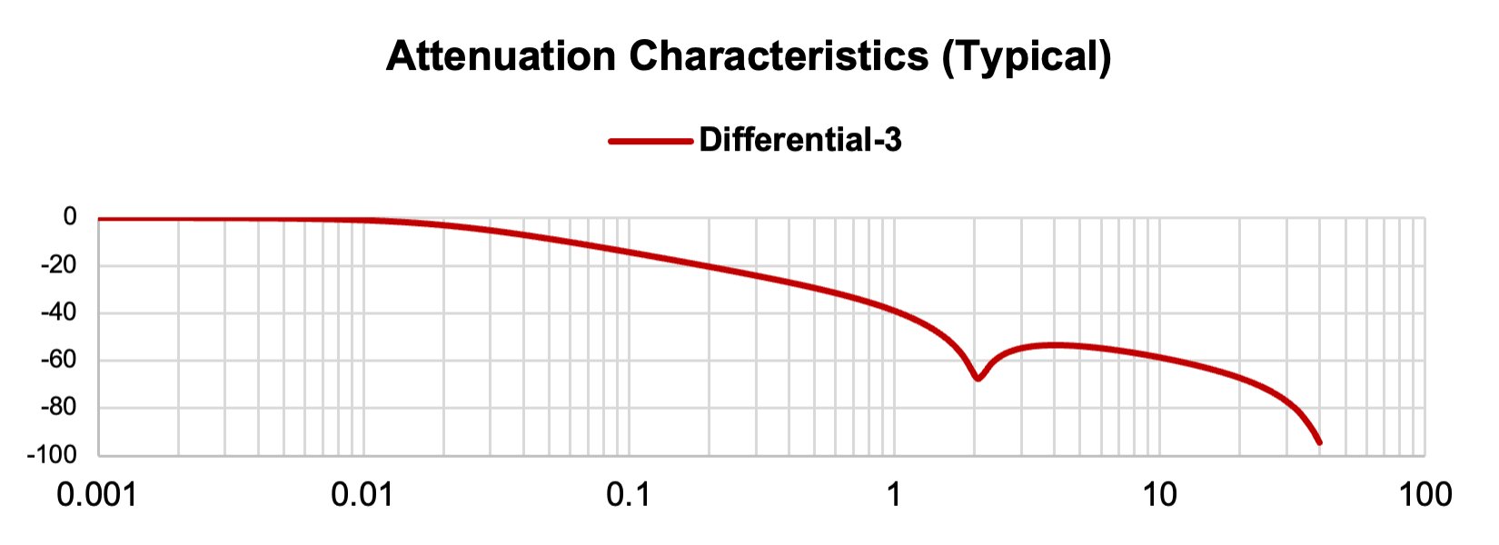
Figure 14
Changing the configuration of components has resulted in a third-order noise filter. Figures 13 and 14 show the resulting attenuation performance using this configuration.
When we compare this performance to the previous filter configurations (Figures 15 and 16), the attenuation performance is improved over a wide frequency range compared to the previous filter configurations.
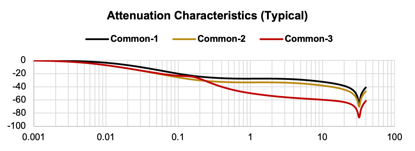
Figure 15
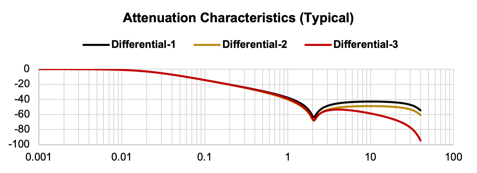
Figure 16
As described, the attenuation performance varies greatly depending on the position of the common mode choke coil and capacitors within the filter. Hence, the configuration of the elements is critical.
Next, let's take a look at the differences in damping characteristics due to differences in CMC core materials.
Figures 18 and 19 show the attenuation characteristics when the core material of the common mode choke of the secondary filter configured in Figure 17 is S15H, nanocrystal, or 7HT.
Element Values:
CMC:
S15H:SCR25XV-150-1R6A010JV (15 A, 1.23 mH)
Nanocrystalline:SCF25XV-150-1R6A010JV (15 A, 2.50 mH)
7HT:SCT25XV-150-1R6A010JV (15 A, 0.80 mH)
Cx: R475N3330CK01M (0.33 µF)
Cy: P295BE471M500C (470 pF)
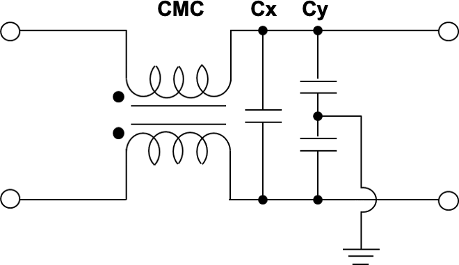
Figure 17
- Common mode attenuation: CMC(Lc)-Cy
- Differential mode attenuation: CMC(Ln*)-Cx
* Ln = Leakage inductance
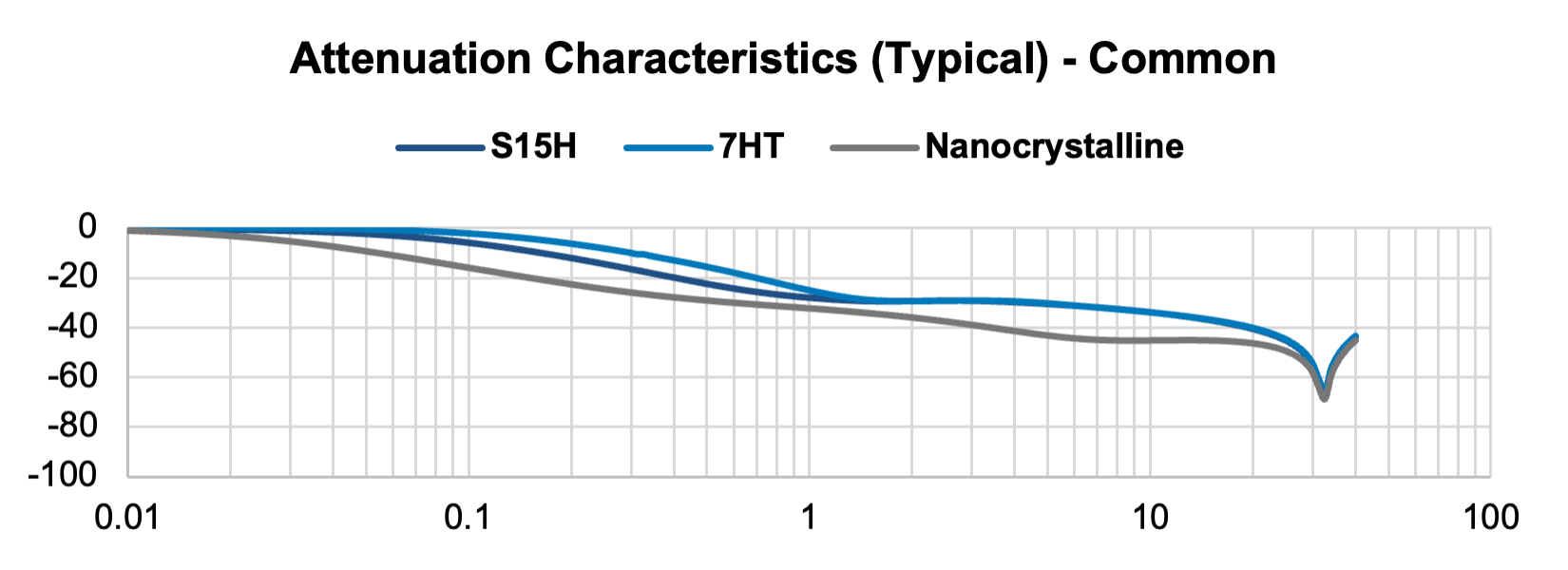
Figure 18
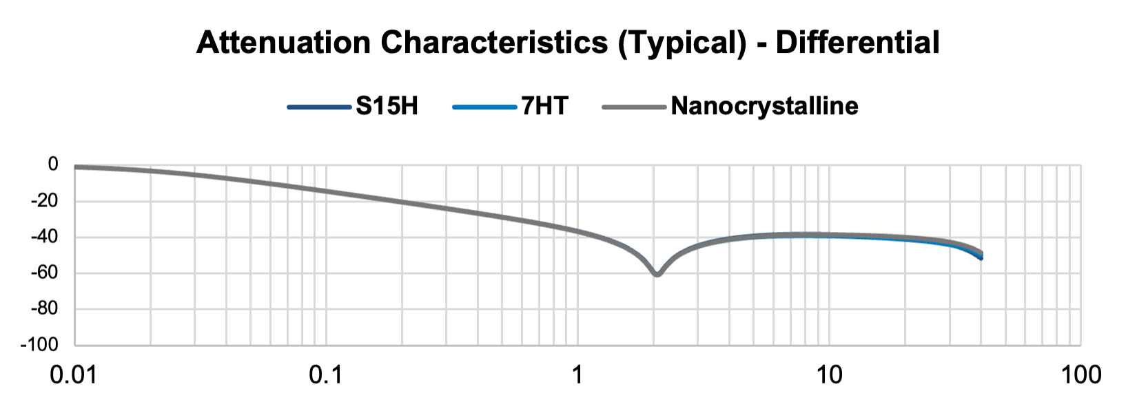
Figure 19
The common mode attenuation characteristics differ depending on the core material of the common mode choke. On the other hand, the damping characteristics of the differential mode are almost the same regardless of the difference in core material. This is because the damping characteristics of differential mode largely depend on the number of turns and winding method.
Next, let's look at the attenuation characteristics of the filter configured in Figure 20, which has two common mode chokes. The characteristics are shown in Figures 21 and 22.
Configuration with two common mode chokes - 1: CMC1-CMC2-Cx & Cy:
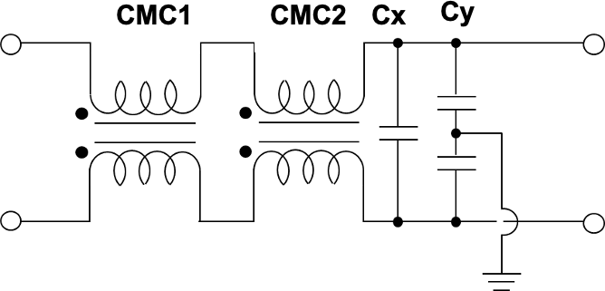
Figure 20
Common mode attenuation: CMC1(Lc)-CMC2(Lc)-Cy
Differential mode attenuation: CMC1(Ln)-CMC2(Ln)-Cx
Element Values:
CMC1:
S15H:SCR25XV-150-1R6A010JV (15 A, 1.23 mH)
Nanocrystalline:SCF25XV-150-1R6A010JV (15 A, 2.50 mH)
7HT:SCT25XV-150-1R6A010JV (15 A, 0.80 mH)
CMC2:
S15H:SCR25XV-150-1R6A010JV (15 A, 1.23 mH)
Nanocrystalline:SCF25XV-150-1R6A010JV (15 A, 2.50 mH)
7HT:SCT25XV-150-1R6A010JV (15 A, 0.80 mH)
Cx: R475N3330CK01M (0.33 µF)
Cy: P295BE471M500C (470 pF)
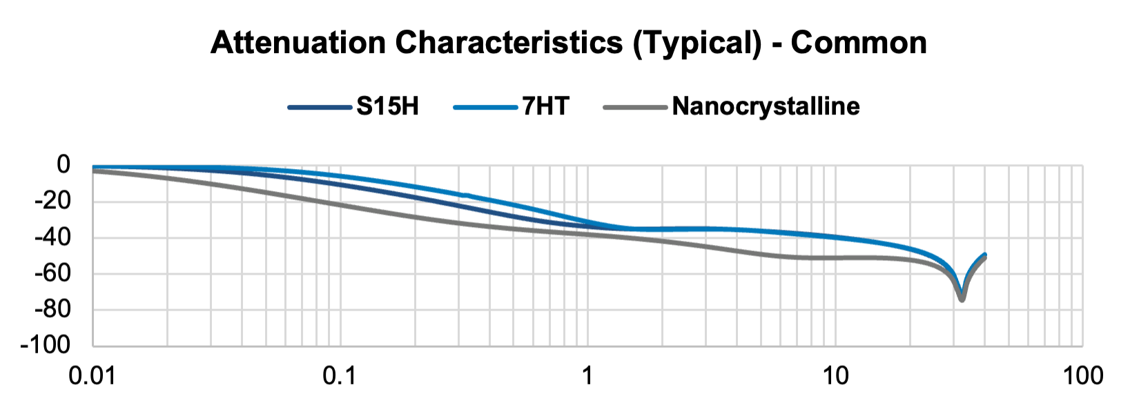
Figure 21
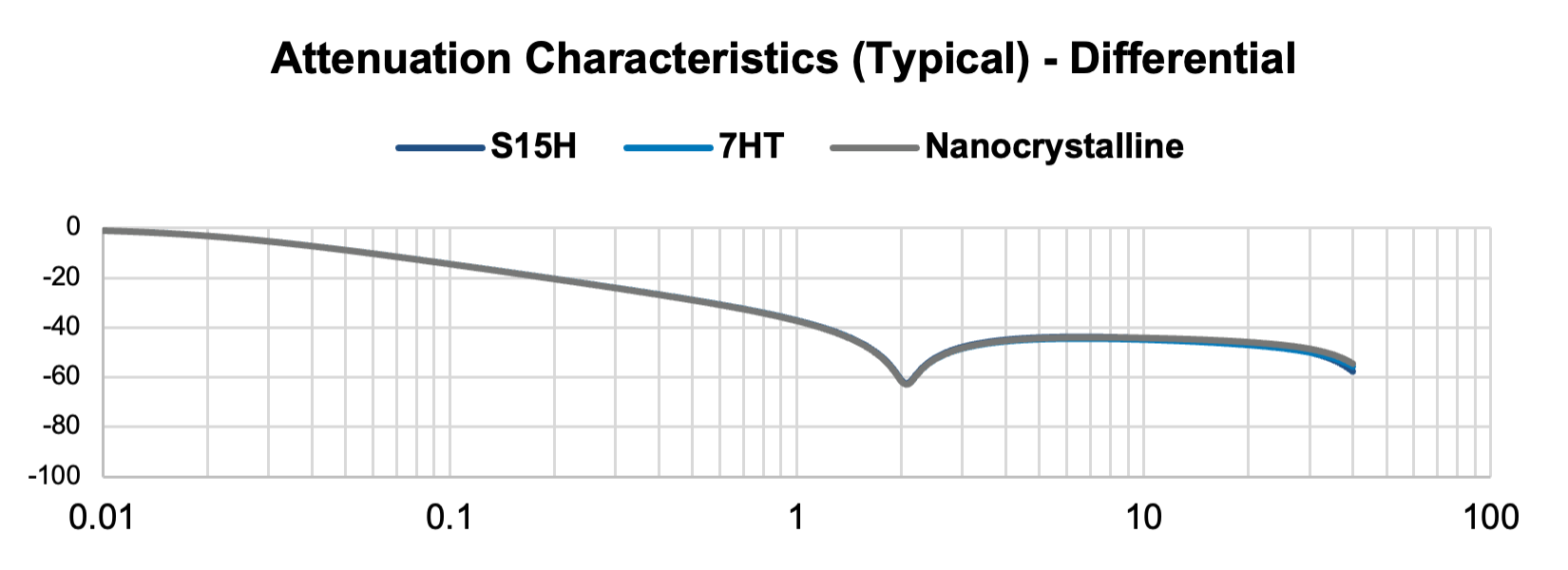
Figure 22
Since the common mode attenuation performance improves due to the increase in CMC component, the difference in characteristics due to the difference in core material is more obvious than when using only one CMC.
Next, Figures 24 and 25 show the attenuation characteristics when the core material of the common mode choke of the third-order filter configured in Figure 23 is S15H, 7HT or nanocrystal.
The filter circuit is then rearranged, and the configuration seen in Figure 23 is simulated.
Configuration with two common mode chokes-2: CMC1-Cx & Cy-CMC2:
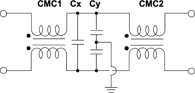
Figure 23
Common mode attenuation: CMC1(Lc)-Cy-CMC2(Lc)
Differential mode attenuation: CMC1(Ln)-Cx-CMC2(Ln)
Element Values:
CMC1:
S15H:SCR25XV-150-1R6A010JV (15 A, 1.23 mH)
Nanocrystalline:SCF25XV-150-1R6A010JV (15 A, 2.50 mH)
7HT:SCT25XV-150-1R6A010JV (15 A, 0.80 mH)
Cx: R475N3330CK01M (0.33 µF)
Cy: P295BE471M500C (470 pF)
CMC2:
S15H:SCR25XV-150-1R6A010JV (15 A, 1.23 mH)
Nanocrystalline:SCF25XV-150-1R6A010JV (15 A, 2.50 mH)
7HT:SCT25XV-150-1R6A010JV (15 A, 0.80 mH)
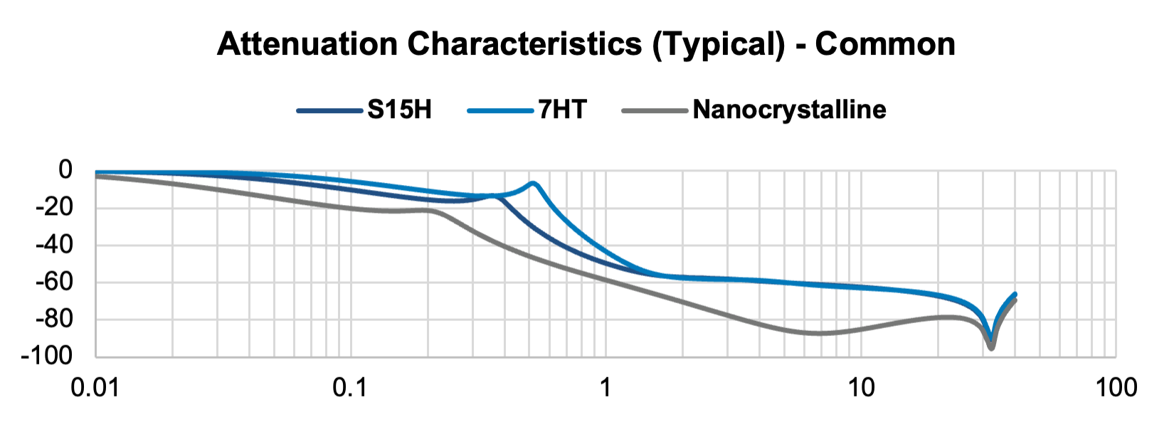
Figure 24
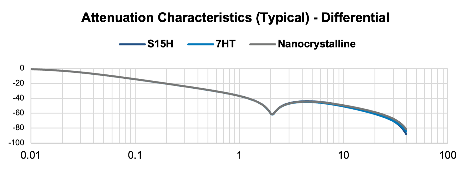
Figure 25
When using a third-order filter, the difference in common mode attenuation characteristics due to the difference in the core material of the common mode choke becomes even larger. Therefore, the selection of core material is also important.
As seen above, one can choose between core materials of nanocrystalline type (SCF-XV) or ferrite S15H (SCR-XV) or ferrite 7HT (SCT-XV). Core sizes available are 19, 25, 29 and 39 mm in both horizontal and vertical orientations. All these series are rated at 1,000 V, with rated current up to 50 A.
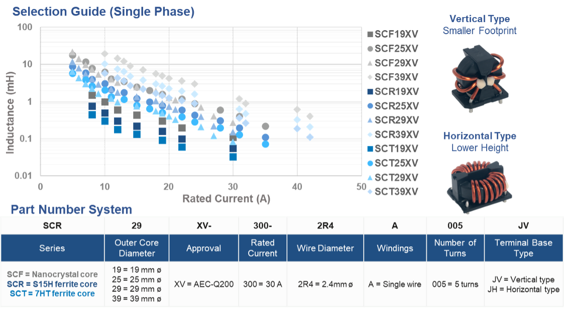
With an increase in BEVs and PHEVs in the automotive market, there is a need for higher voltage componentry. KEMET’s SCF-XV, SCR-XV and SCT-XV series offer solutions to this need.
Significant benefits are:
KEMET’s automotive chokes can provide optimal EMI performance for automotive products, where electrification is accelerating.
Customization support is offered, so please contact your KEMET sales representative if you have specific requirements.