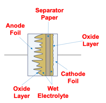
Figure 1 – Typical wet electrolytic capacitor (Courtesy of KEMET)
Since capacitance is a function of surface area, aluminum foils are first etched to create a rough contour with maximal contact area, resulting in high capacitance and optimal CV-value.
A second foil layer and a paper separator are added to fully complete the capacitor structure, producing an excellent terminal contact with this electrolyte. This aluminum-electrolyte-paper sandwich is then rolled or “wound” into a can and sealed with two terminals.
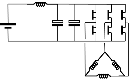
DC-link capacitors are used in order to provide a stable DC-voltage, limiting voltage fluctuations even under high ripple current loads and fluctuations created by the inverter. The DC-link capacitors are acting as a local energy source, connected to the DC- board-net close to the power electronics (low impedance).
Key Requirements, for Automotive DC-Link Capacitors
An EMC filter is often used to protect the board-net from voltage spikes created by the switching power electronics.
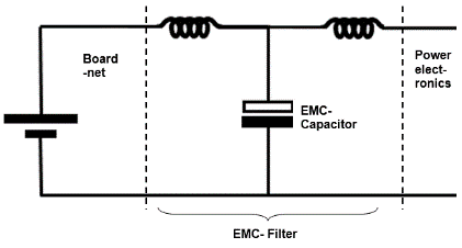
The requirements for an EMC filter capacitor in automotive inverters is similar to that of DC-link capacitors.
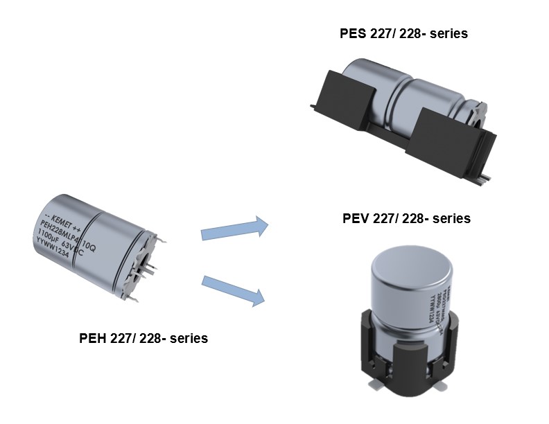
Increasing levels of miniaturization have forced the development of SMD alternatives to what was once only served by through-hole options.
The PES and PEV series of SMD aluminum electrolytic capacitors is based on the successful PEH and PEG series of through-hole radial crown capacitors. This introduction brings the expectations of high CV and high ripple current performance to an SMD solution.
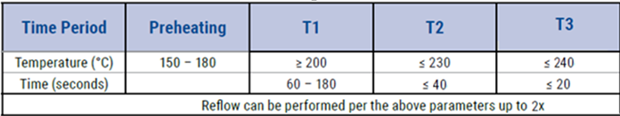
The following considerations should be remembered when implementing a reflow process:
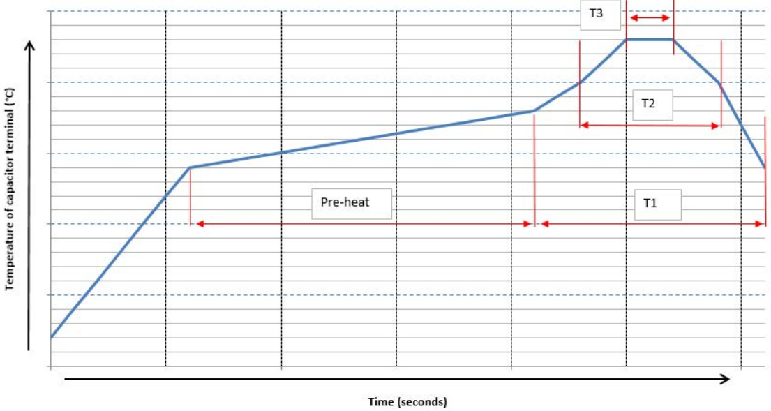
Recommended reflow profile:
Solder Paste Alloy:
Solder passed allow should be selected to be suitable for the above recommended reflow profile. Sn/Ag or Sn/Ag/Cu allows with recommended peak solder temperatures in the range of 235C to 240C should be used.
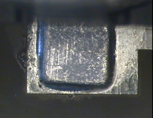
Example of Successful Reflow
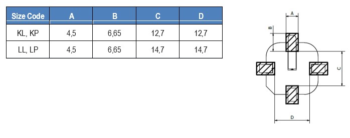
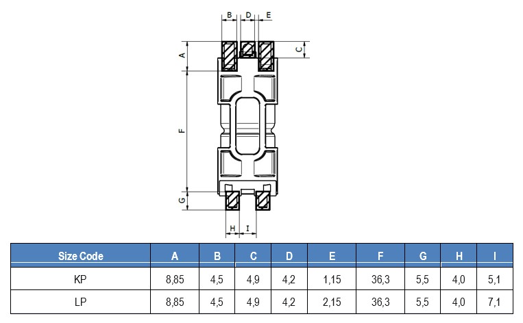
PEV22x Series Footprint:
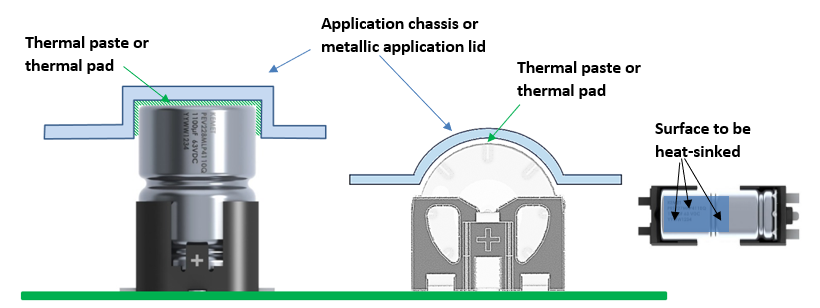
The ripple current capability of the capacitor is further increased if the capacitor body is mounted to a chassis or metallic body with low thermal resistance. The information in the datasheet shows both natural convection and heat-sinking conditions.