Tantalum polymer capacitors are popular in many decoupling applications including high performance DC to DC converters. This created a perfect fit for polymer capacitors in telecom and industrial high performance applications. Now the automotive segment is showing an increased demand for these type of capacitors for use in infotainment and advanced driver assistance systems (ADAS). Most automotive applications require passive components to be qualified to the Automotive Electronics Council’s AEC-Q200 Stress Test Qualification for Passive Components. KEMET Electronics has addressed this need by developing new processes and materials to offer the market’s first polymer electrolytic capacitors qualified to AEC-Q200.
This application note introduces polymer electrolytic technology, the electric performance of these parts, advantages relative to other capacitors, and how the commercial-grade product was improved to pass the stringent AEC-Q200 guidelines.
Conductive organic polymeric materials were discovered by Alan Heeger, Alan MacDiarmid and Hideki Shirakawa. They were awarded the 2000 Nobel Prize in Chemistry for the discovery and development of conductive polymers. One of first industrial applications of new polymer organic material was to replace manganese dioxide (MnO2) in tantalum capacitors.
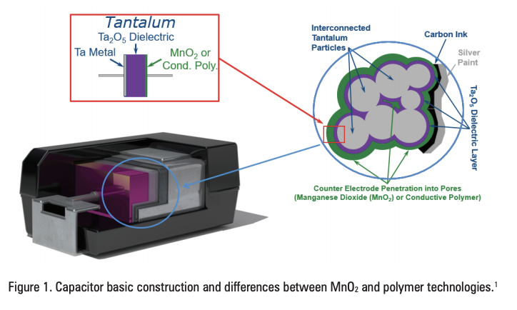
The basic capacitor construction consists of two dielectric plates separated by a dielectric. In the case of electrolytic capacitors, one plate consists of a positively charged anode while the other consists a negatively charged anode. The anode of a tantalum capacitor is a porous pellet of sintered Ta metal. This porosity creates a large surface area within the pellet structure, which results in the tantalum capacitor’s characteristic high capacitance. The dielectric is tantalum pentoxide (Ta2O5) which is formed by an electrochemical anodic oxidation process (2Ta + 5H2O Ta2O5 + 5H2). The cathode is a semiconductor material, either MnO2 or a conductive polymer. A carbon layer chemically isolates the MnO2 or the conductive polymer from the external silver coating. For surface mount applications, the capacitor element is attached to a lead frame and encapsulated with an epoxy compound. The overall size and dimensions are consistent with EIA standards.
The important properties required for the primary cathode material in a solid electrolytic capacitor are (a) the ability to impregnate small pores, (b) high conductivity, (c) low cost, and the most restrictive requirement, (d) the ability to “self-heal” leakage sites in the dielectric layer.
In traditional MnO2 technology, joule heating at a leakage site converts the primary cathode material to a non-conductive material (MnO2 Mn2O3). The polymer technology also presents a healing effect by oxidization, evaporation or decomposition.
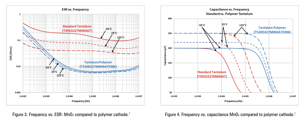
Polymer tantalum capacitors achieve much lower equivalent series resistance (ESR) as compared to tantalum capacitors built with MnO2 cathodes. The resistivity of the polymer material is in range of 0.05 – 0.50 ohms per centimeter. That is significantly lower than MnO2, which is in the range of 5 – 10 ohms per centimeter.
The temperature coefficient of resistance (TCR) for that ESR is much lower than the standard MnO2 capacitor, although the TCR is negative for both, as shown in Figure 3.
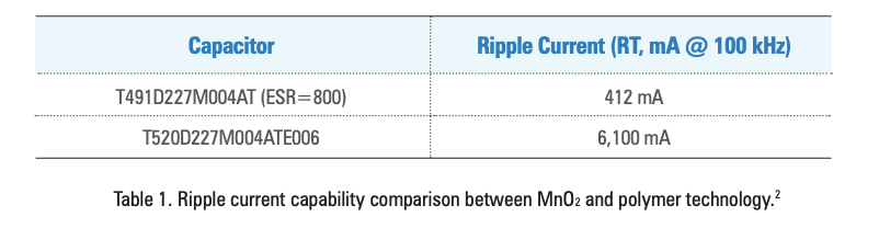
An effect referred to as “capacitance roll-off” is illustrated in Figure 4. The capacitance of an electrolytic capacitor is reduced as frequency increases. Because polymer capacitors have such low ESR, they maintain high capacitance at high frequencies relative to their MnO2 counterparts.
At low frequency, the capacitance is dominated by the temperature dependence of the Ta2O5 dielectric constant, which is the same for both types of capacitors.
The maximum allowable ripple current capability is a factor of the capacitor’s ESR. High ripple current capability is possible with polymer capacitors due to very low ESR. Table 1 compares two tantalum capacitors and their rated ripple current. The T491 capacitor has a MnO2 cathode while the T520 has a polymer cathode.
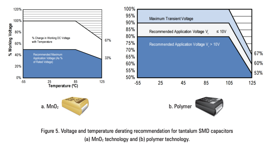
The most common failure mode for a tantalum capacitor is when voltage is applied to the part, typically when a system is powered on. To reduce this failure rate, manufacturers provide recommended voltage derating. Figure 5 shows the voltage derating differences between an MnO2 and polymer capacitor. Polymer capacitors maintain a lower recommended derating.
The soft conductive polymeric film reduces mechanical stresses inside the capacitor element amid extreme temperature changes, for example, during reflow soldering. Smaller mechanical stress on the dielectric layer results in fewer and less extreme fault sites.
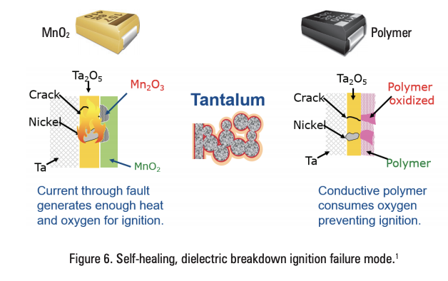
The cathode material provides some self-healing for the fault sites in the dielectric layer. If a fault site is created that the cathode layer is unable to heal, a failure may occur. When this occurs, the intrinsic chemical characteristics of MnO2 and the conductive polymer determine an important difference in the failure conditions.
MnO2 is an oxide semiconductor that acts as oxygen donator during the self-healing reaction (4MnO2 2Mn2O3+O2). When large current flows through a dielectric fault, the oxygen can react with the Ta creating a thermal event, also known as ignition.
The conductive polymer, however, is not an oxygen donator. This difference enables a benign or safe failure mode. With a polymer cathode, the polymer will locally oxidize due to the heat created by the high leakage current, healing the leakage site and preventing ignition (Figure 6). In this case, the capacitor is still considered failed as a short, but the failure mode does not result in ignition.
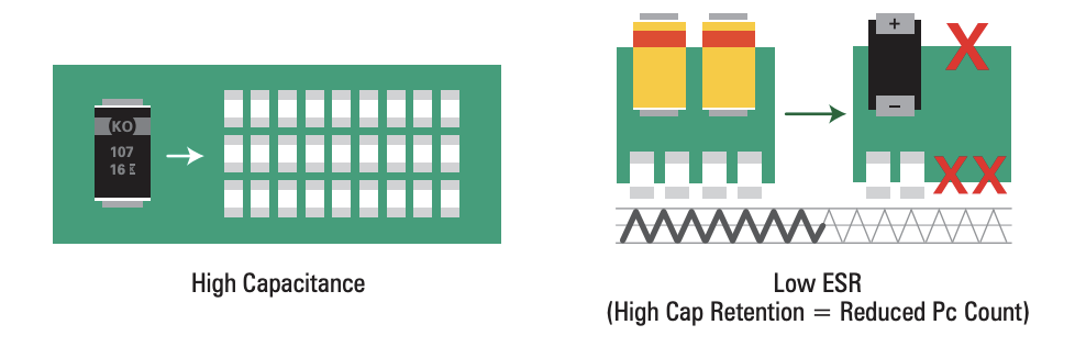
When considering these performance characteristics, polymer electrolytic capacitors can provide a variety of design advantages.
Fewer components result in lower cost. The high capacitance in a small package is referred to as high volumetric efficiency. Polymer capacitors are stable in regards to voltage, temperature and frequency, which means they can typically replace several ceramic or traditional MnO2 capacitors in a design. Fewer parts also means fewer pick and placements.
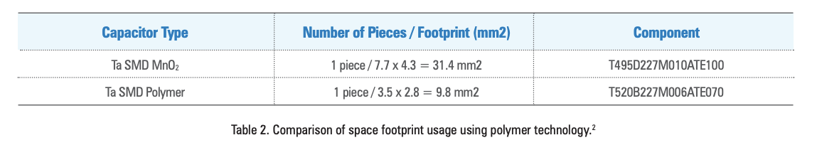
Each generation of electronics becomes smaller and thinner. The low profile height of polymer electrolytic capacitors potentially reduces the overall height of a system. When moving from a 50% MnO2 derating to a 10% polymer derating, lower voltage parts can be selected, which are typically smaller.
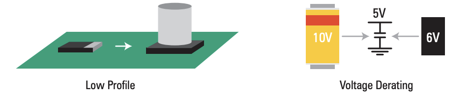
Table 2 compares the electrical characteristics from a customer’s application. The DC to DC converter required 220 µF for a 5 V rail. Using a polymer component, surface area was reduced by 68%
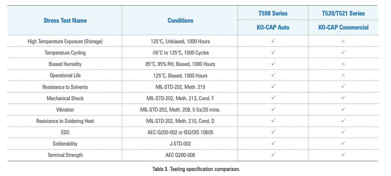
Since its introduction, polymer technology has been very popular in every electronics segment, except automotive. The reasons were not related to the electrical characteristics but because polymer capacitors could not pass the AEC-Q200 qualification, specifically tests involving high humidity and high temperature.
Table 3 compares the areas where commercial polymer capacitors (T520/1) struggled with AEC-Q200 tests to the performance of the T598. KEMET introduced the T598 Series as the first polymer electrolytic capacitors to pass AEC-Q200 qualifications.
The results of our initial effort to improve the environmental performance were published at the 2014 CARTS conference by Jayson Young et al.3 Research and development work focused on addressing the two failure mechanisms polymer counter electrode degradation and ionic migration.
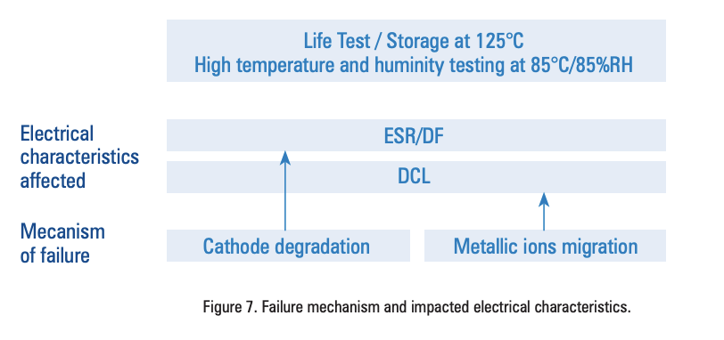
The polymer cathode degradation directly increases the ESR and dissipation factor of the component. Degradation can be seen with parts when subjected to two tests: (1) life test and storage at 125°C, and (2) high temperature and humidity (85°C, 85% RH, biased).
From previous evaluations, extended exposure to air at elevated temperatures caused the polymer material to oxidize.4 This suggested that the increased ESR and DF from the 125°C life and storage test was due to interstitial diffusion of oxygen, which resulted in oxidation of the polymer cathode layer. The diffusion occurred through both the epoxy encapsulation and interfaces between the lead frame and epoxy.
During the high temperature and high humidity tests, humidity permeated the component through the same lead frame and epoxy interfaces, causing metallic ionic migration. This migration results in an increase of the dielectric leakage current.
The primary design change in the new T598 Series is a new moisture protection layer. The second major improvement is a new epoxy material which reduces the permeability of oxygen and humidity. The case integrity was also improved with this new material.
With the new case material and moisture protection layer in place, the T598 mitigates the negative impact on ESR, DF and leakage current when parts are exposed to high humidity
Figure 8 demonstrations the ESR improvement of a T520 (commercial polymer) and a T598 (new automotive polymer) when exposed to the AEC-Q200 85°C/85% RH test.
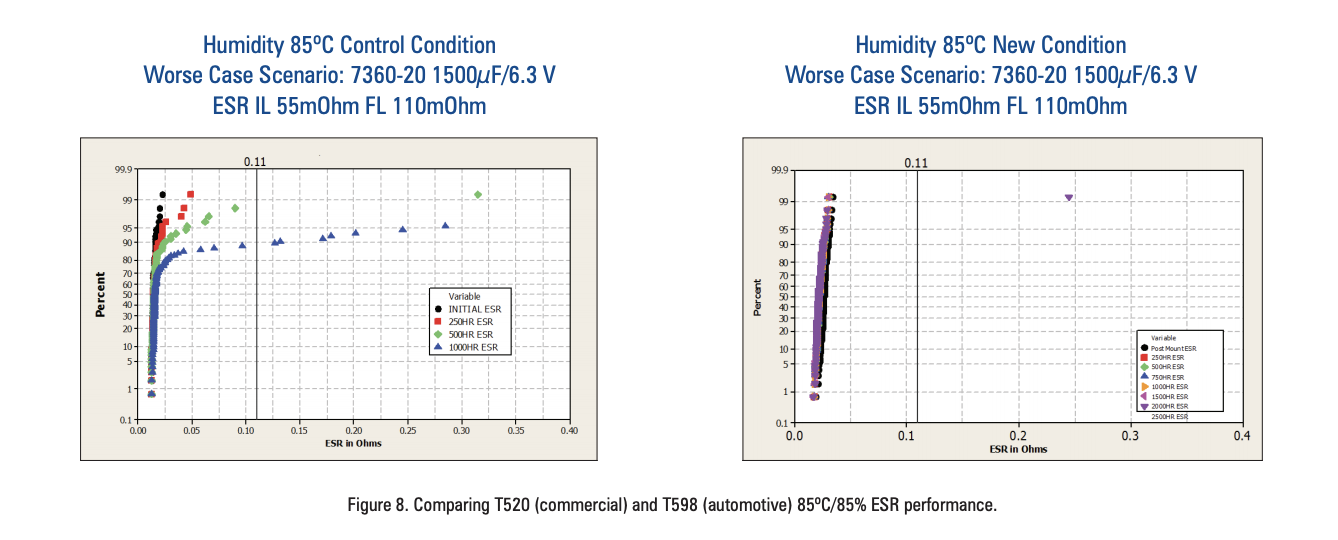
The EIA7360-20 case size with 1500 µF, rated for 6.3 V (T520H158M006ATE055) was chosen because it represents this test’s worst-case challenge. This capacitor size presents a large surface area of epoxy with a large internal anode, minimizing epoxy thickness.
In the control group, the negative impact in the polymer degradation starts to be seen at 250 hours and continues to degrade. At 1,000 hours, 40% of the population exhibits drifting. Out of 100 capacitors, 8 have already shown parametric failure, with higher than post-acceptance limit. In contrast, the new process conditions show stable ESR past 1,000 hours. One capacitor failure can be seen under these harsh conditions after 2,000 hours.
Examples of the ESR and DC leakage (DCL) are shown in Figure 9. This data is based on an EIA7343-31 case size, 100 µF capacitor rated for 16 V (T598D107M016ATE050).
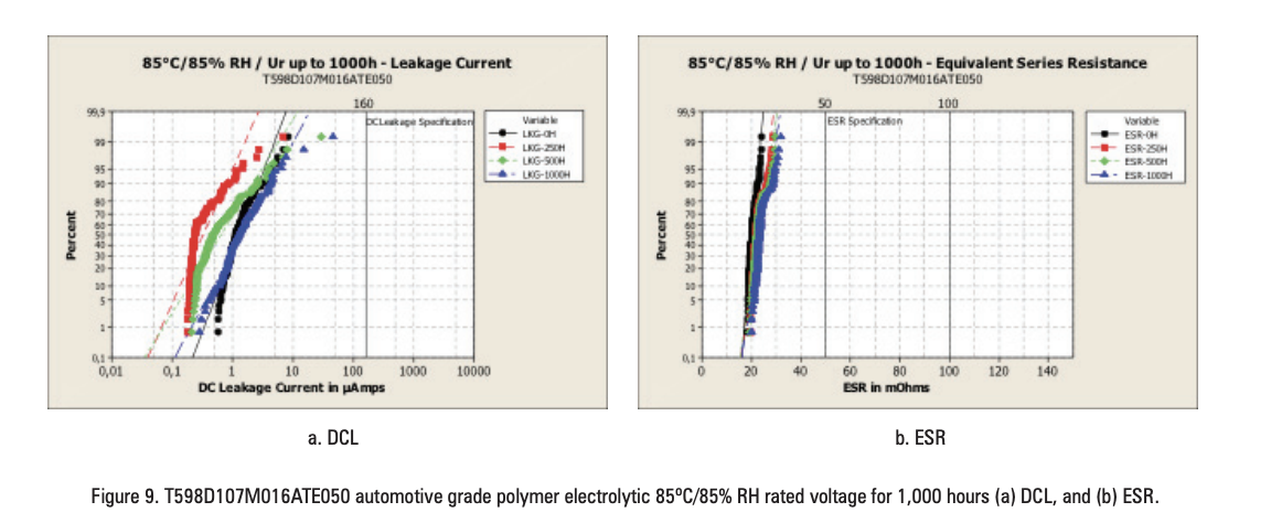
Notice that the leakage current drops from the 0 hour measurement to the 250 hour measurement. This shift is related to the self-healing effect of the polymer cathode and is common with tantalum capacitors. The acceptance criteria post-test is within the initial specified limit of 160 µA.
The ESR shows stable performance up to 1,000 hour testing with the entire population within the initial specified limit of 50 mOhm. The behavior of ESR provides experimental evidence for the improvements mentioned.
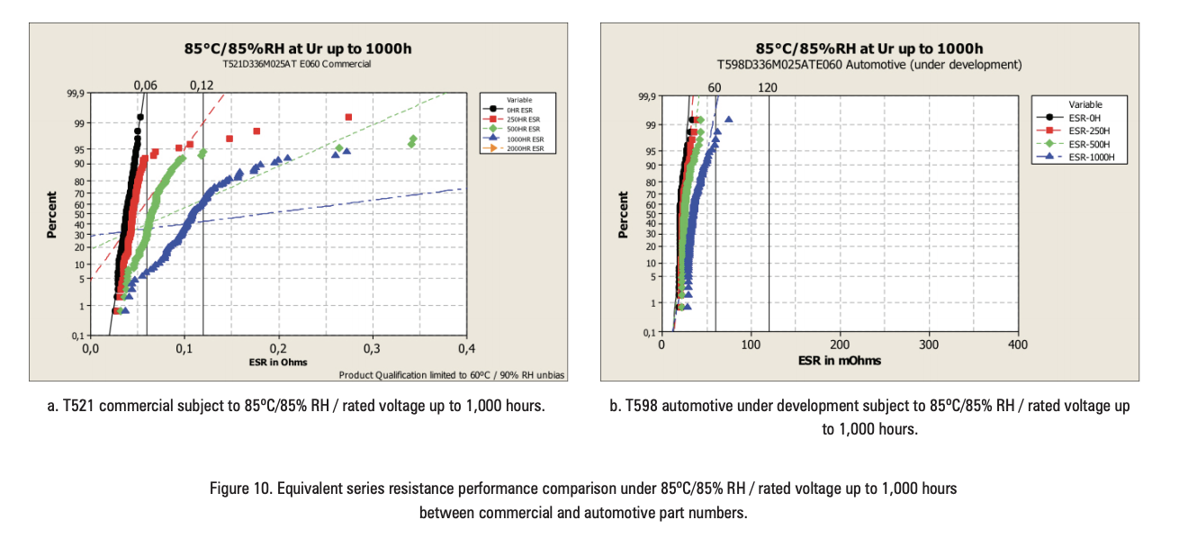
Research and development continues to expand the full AEC-Q200 capabilities to higher-rated voltages. Currently, 25 – 50 V voltage ratings are under development. The preliminary results are positive. Figure 10 compares a commercial 25 V capacitor (T521V336M025ATE060) to an under development automotive 25 V capacitor (T598D336M025ATE060).
The T598 includes these new design changes, achieving the industry’s first AEC-Q200 qualified polymer electrolytic capacitor. Initial part number offerings includes capacitance up to 330 µF and 16 V rated voltage.
For over 15 years, polymer electrolytic capacitors have been successfully utilized in high volume applications such as laptops, tablets and mobile phones. The full AEC-Q200 qualification of the T598 eliminates the roadblock polymer electrolytic technology by the automotive segment.
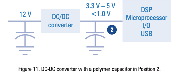
The electrical and physical benefits of polymers can be employed by automotive designers in infotainment and advanced driver assistance (ADAS) applications, such as in the DC-DC converter shown in Figure 11.
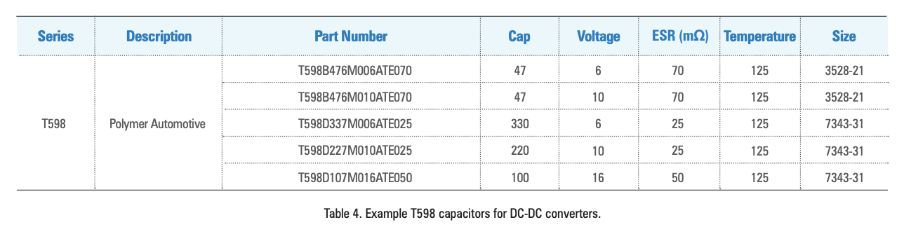
For such an application, the capacitors in Table 4 are recommended. Visit the T598 product page for detailed information and specifications on the T598 Series.
KEMET’s new T598 Automotive Polymer Electrolytic capacitors are a result of several years of research and development efforts. By utilizing new processes and materials, it was possible to introduce the first polymer electrolytic capacitor fully qualified to AEC-Q200 Revision D.
KEMET will continue its development efforts to expand the range of components available for harsh environmental conditions.
Cristina Mota-Caetano and Jane Ye