This application note describes the items to consider when integration electro-active polymer actuator onto flexible and rigid bodies. This application note considers the following items:
For product specifications, product part numbers and safety information please refer to the datasheet “KEM_P0106_FFAA”.
It is recommended to:
The following parameters/specifications must be considered when selecting material for the user facing surface:
Resistance to bending
Wear rate
Water Resistance
Conformability
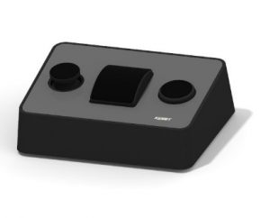
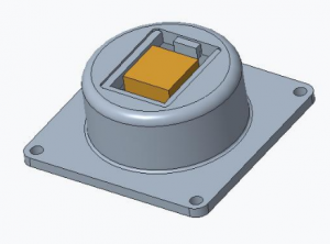
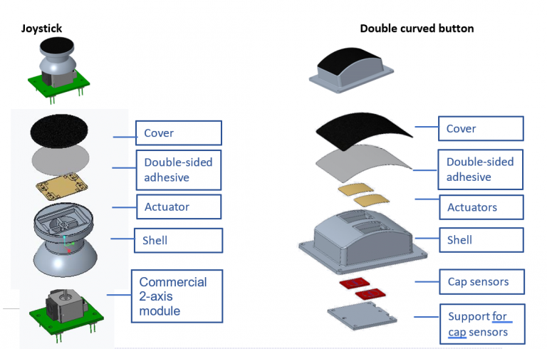
The above assembly integrates three different shapes, which can easily be found in several human-machine interfaces: buttons, joysticks, touch pad. It is built with the integration of four actuators in three hard button shapes.
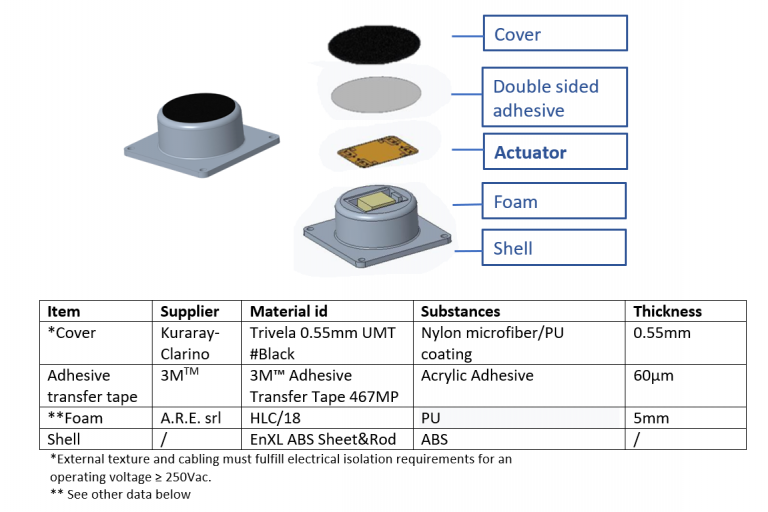
Each button has the same integration structure as per the following:
In order to obtain the best performances, the actuator supporting structure should be designed to:
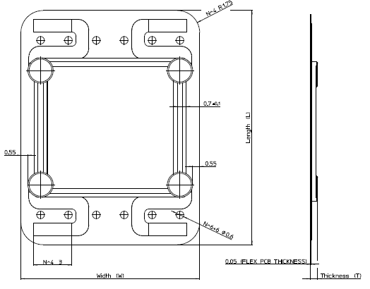
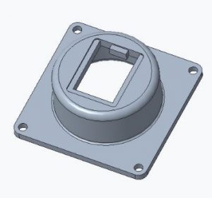
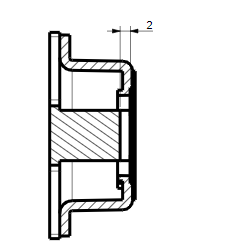
The assembly above shows an example of opening. Its dimensions are shown in the table below.
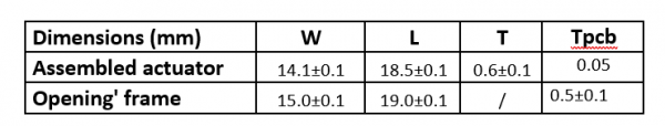
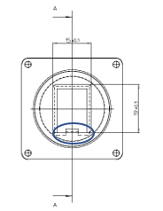
The frame where to put the actuator has a tooth (circled area) to facilitate the actuator position, where the soldering points are.
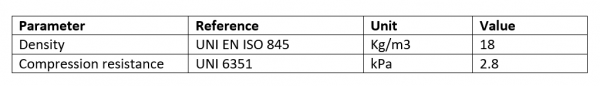
The active part of the assembled actuator can be supported by a thin foam layer placed below the actuator itself. The foam support can be placed into a cavity in the mechanical body, drive wires can be fed through holes in the cavity if space allows. Below are some characteristics of foam options of various durometers.
In the current example, the foam used has the following characteristics:
Electrical connections to the actuators should be done in such a way as to:
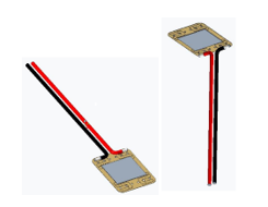
Soldering can be done following the same plane as the actuator or normal to it (see picture above). It is important to provide adequate strain relief.
Note: Polarity is not relevant; actuators are AC voltage powered.
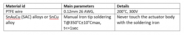
Important wiring parameters
Both heat activated or pressure sensitive adhesives can be used to fix the assembled actuators to the user facing surface. The choice depends on the shell material and on the user facing surface material. Heat activated adhesive should be avoided on the area where the actuator is since the bonding temperature must not exceed 100°C on the area where the actuator is. Mechanical adhesion is easier compared to heat activated adhesion: it is suggested to avoid air bubbles within the adhesion area.
Cover should be chosen to avoid actuator performances reduction due to stiffness or thickness. Moreover, it has the following functions:
Other points to facilitate assembly include:
In addition to functionality, the actuator should be tested for capacitance and insulation resistance after assembly.
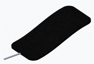
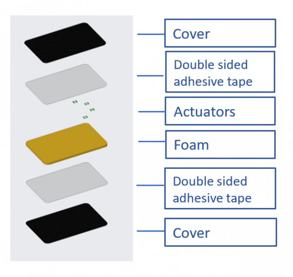
The actuators may also be integrated onto flexible, non-rigid bodies. This allows to for the reliable transfer of energy between the actuator and the subject when embedded into a flexible substrate. The table below shows materials involved in the process of integrating onto flexible bodies.