In principle, charging batteries within electric vehicles (EVs) is straightforward. One must convert an external voltage source (AC or DC) to an appropriate output voltage that achieves constant current followed by continuous voltage energy transfer into the battery. Doing this safely, however, is an entirely different proposition with a host of engineering challenges. The difficulty exacerbates when chargers are required to output high levels of power for quick charging performance while also being designed for ease of use.
To codify the safety requirements for EV chargers, regulatory agencies worldwide have defined standards to which every charger topology must be upheld and are detailed in the IEC 61851 for conductive charging systems. Four charging modes have been defined: Mode 1 involves connecting the vehicle directly to the AC power grid, which is typically not allowed in most countries. Mode 2 requires an intermediate control system (IC-CPD) between the AC power grid and the vehicle to monitor for safety issues and is connected to an AC power outlet socket. This device is usually a mobile device one would carry in the car's trunk. Mode 3 relies on a dedicated safety control system that is permanently connected to the AC power grid; these are the typical AC charging stations seen in many parking lots and garages and installed at private homes. Mode 4 is the only DC-based system, and it converts AC grid energy into DC voltage for charging the vehicle while also monitoring safety. Each of these modes has a dedicated safety standard to govern the performance requirements of the associated equipment. IEC62752 / UL2231-2 is a representative standard for Europe and the USA that covers Mode 2 chargers. IEC62955 / UL2231-2, similarly, covers Mode 3 chargers.
A critical parameter in these types of safety standards is the residual operating current, which is effectively the leakage current that finds a path to ground through some means other than the AC power grid. The residual operating current is a critical parameter because this unknown current path could very well be a human interacting with the system. Therefore, monitoring the magnitude of this current is a primary safety concern. For Mode 2 chargers, the residual current is restricted to 30 mA AC and 6 mA DC. Mode 3 chargers depend on the rated AC current, which residual AC current is allowed. It is 60 mA if the rated current is 125 A, but no AC chargers on the market support more than 22 kW. Therefore realistically, the AC residual current here is also 30 mA maximum. The 6 mA limit applies to both Mode 2 and Mode 3 chargers for residual DC currents.
Charging equipment must contain a highly sensitive device for measuring very small residual current flow in the presence of very large nominal currents to satisfy safety standards. As it is a safety device that can interrupt the charging process, it needs to be reliably working over a wide temperature range with high accuracy. In addition, Mode 3 requires that it withstands up to 3,000 A inrush or short currents without damage.
The fluxgate (FG) current sensor is one of the most robust solutions for measuring residual current. As shown in the figure below, the AC primary lines are passed through a magnetic core just before these lines enter the charging line toward the vehicle. Passing the lines through a magnetic core is an important distinction compared to any other technique as these large, high-current cables require no modification, a non-invasive measurement technology. A pickup coil is wrapped around the same core and integrated into an external low-voltage oscillator circuit. Imbalances in the high current feed and return paths couple into the pickup coil through the magnetic core. As a result, any residual current in both AC and DC can be detected by a change in the oscillator frequency or oscillator duty cycle, respectively. For DC residual currents, it can also identify the direction of the DC current.
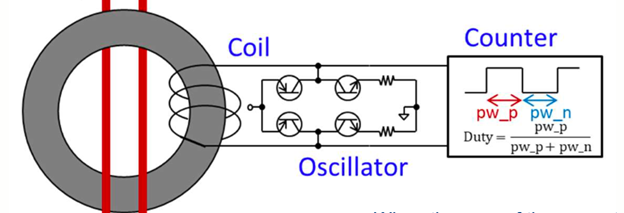
Figure 1 - Fluxgate current sensor
This innovative device can sense very small leakage currents in very large charging currents and is completely isolated electrically from the monitored circuits. As a result, the low voltage output can be directly processed to create alarms that immediately shut down the charger in an over-leakage threshold condition.
KEMET's patented FG sensor solution is shown in the figure below. Primary conductors pass through a magnetic core, and the pickup coil and oscillator are used to generate AC and DC pull-down alarms on dedicated pins. An additional conductor is included within the magnetic core to self-test the FG sensor. A 5 V test signal can be applied to intentionally create residual current alarms and validate the sensor's health before a charging process is initiated. Typically, this is required by the UL regulation. Analog output is also included for optional analysis of the FG signal by an external analog-to-digital converter (ADC) and microcontroller (MCU). The optional analysis can be of interest in pre-evaluating the residual current situation before reaching a threshold. For example, to inform the charger owner that there is potentially a reason for maintenance or to evaluate if moisture is present in the charger's device.
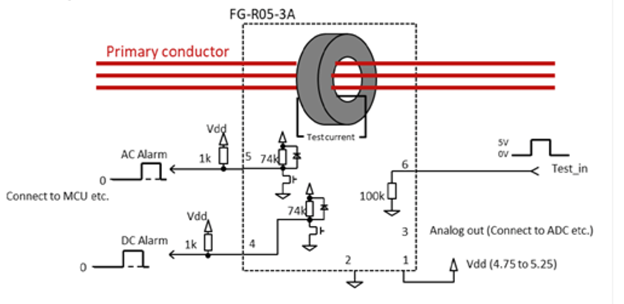
Figure 2 - KEMET’s FG-R05-3A fluxgate current sensor internals
KEMET’s FG sensor lineup includes the FG-R05-3A for Mode 2 chargers and the FG-R01-4A, FG-R02-4A, and FG-R05-4A for Mode 3 chargers. Each flavor fits within a highly compact footprint and is available in different orientations and mounting styles.
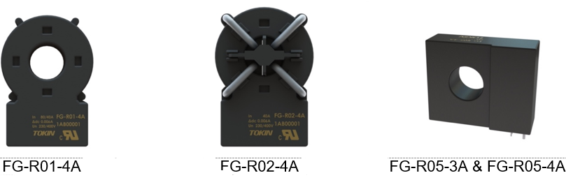
Figure 3 - KEMET’s FG-R sensors’ different form factors
The FG-R series is rated at 105°C max ambient temperature: the highest in the industry. An example is shown in the following figure, where the magnetic core passthrough is visible along with the simple six-pin interface.
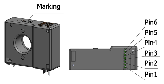
Figure 4 - KEMET FG-R05-3A fluxgate current sensor
The most important feature of the KEMET FG-R lineup is that these devices each comply with all applicable regulatory standards. With KEMET's solution, the customer only needs one sensor and can ship anywhere in the world, significantly simplifying the bill of materials, maintenance, and complexity.
The fluxgate current sensor is a remarkable modular device ideally suited to safely monitoring residual currents in EV chargers. The open-loop, or passthrough operation, makes product integration as simple as possible, while the electrically isolated monitoring circuitry bolsters safety. KEMET's fluxgate product lineup is affordable, compact, and compliant with numerous regulatory standards, and pre-tested EMC compliance where possible, was tested with the full lineup for emissions and immunity. These components should be a staple in the toolbox of any design engineer looking to maximize product safety while simplifying system integration.