Electromagnetic Compliance (or EMC) refers to the rules and regulations set forth to ensure that electronic appliances do not adversely affect each other. This interaction may be due to unwanted radiation of electromagnetic waves or through the noise on common power supply lines. The latter - referred to as conducted emissions - plays an important role for all appliances powered by AC mains.
To ensure that AC-powered appliances coexist peacefully, EMC demands that two kinds of noise do not feed back into the supply lines: differential and common mode. Differential noise is expressed between the power phases themselves, whereas common mode noise is seen on all power phases equally with respect to earth ground. Each type of noise can be suppressed with a specific low-pass filter design. By designing these filters properly and cascading them, conducted noise can be suppressed to levels that will not interfere with any upstream devices.
An example filter design for single-phase EMC is shown in the figure below, where the left-hand LCx filter eliminates differential noise, and the right-hand LCy filter handles common mode noise.
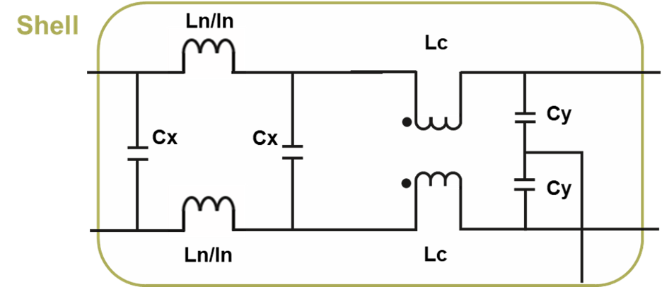
Figure 1 - Two stage line filter for single phase EMC
Depending on the characteristics of the load appliance (e.g., a switching power supply with high-speed SiC FETs or a simple AC motor), proper selection of the filter components is critical to achieving EMC requirements.
High-power industrial equipment often demands more power than a single-phase AC supply can deliver. For this reason, it is typically powered by a three-phase AC supply. Examples include large industrial robots, motor drives, and large medical devices like MRI scanners. Just like their single-phase counterpart, three-phase equipment requires filtering for EM compliance, but with an additional channel to contend with. This additional channel, along with the higher current loads associated with this type of equipment makes the three-phase filter design exponentially more complicated. A representative schematic is shown in the figure below.
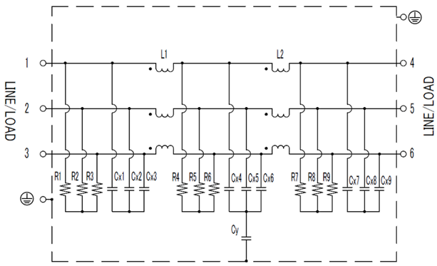
Figure 2 - Three-phase line filter schematic
Common mode noise is still filtered using the Cy capacitor, while differential noise is filtered on each combination of phases by a dedicated Cx capacitor along with a complex three-winding inductor on a common core. The component count is three times greater than the single-phase solution, even though only one additional phase is present. Achieving high-quality filtering while optimizing for space and cost is a very difficult challenge.
Depending on the electrical characteristics of the load device, line filters must be specified by certain performance specifications to properly achieve EMC. The input voltage and average/peak load current are the two fundamental qualities that begin to define filter construction. Secondary requirements often include peak withstand voltage, insulation resistance, and leakage current. Finally, environmental and physical constraints must be considered including operating temperature range, physical shape, and weight. An example line filter specification for KEMET’s GTX three-phase filters is shown in the table below.
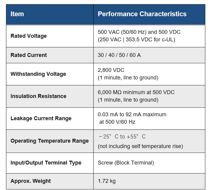
Table 1 - Line filter specification table
It is common for filter suppliers to provide units that integrate three individual line filters in a single enclosure as a three-phase filter to deliver a space-efficient solution. These designs can be fully custom, or configurable off the shelf. For example, many suppliers offer a multitude of options for a particular filter including the selection of individual capacitor values.
Physical size is one of the most important considerations for line filter selection. It directly impacts the form factor of the final product and in some applications, may adversely affect performance. One of the dominant components in determining filter size is the inductor core of the common mode and differential chokes. A variety of core materials can be used, but the latest technology advancement makes use of nanocrystalline amorphous metal. These cores are produced by rapidly cooling molten metal, and then heat treating it to generate very small crystalline grains. The result is a core with much higher saturation magnetic flux density and permeability along with excellent temperature characteristics. As a result, the core can be reduced in size and weight for the same overall performance when compared to more traditional technologies. An example is shown in the figure below where the attenuation over frequency is shown for a nanocrystal choke compared to two standard chokes.
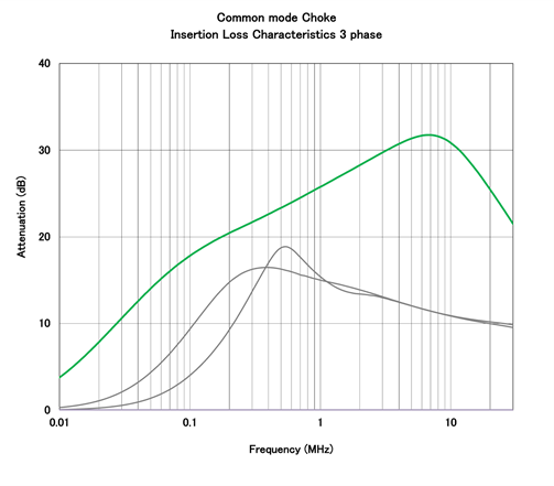
Figure 3 - Standard (black) vs nanocrystal (green) common mode chokes
Nanocrystalline inductor technology has enabled KEMET to produce the GTX three-phase family of 24 off-the-shelf three-phase filters to give power supply designers a broad choice of space-efficient options. The GTX three-phase family is available in rated currents or 30, 40, 50, and 60 A. Each current rating is further divided into a choice of 6 Y capacitors combinations. Compared to conventional filters of the same performance, the GTX three-phase family is 68% smaller and 28% lighter. The attenuation characteristics of each of the capacitor options are shown in the figure below.
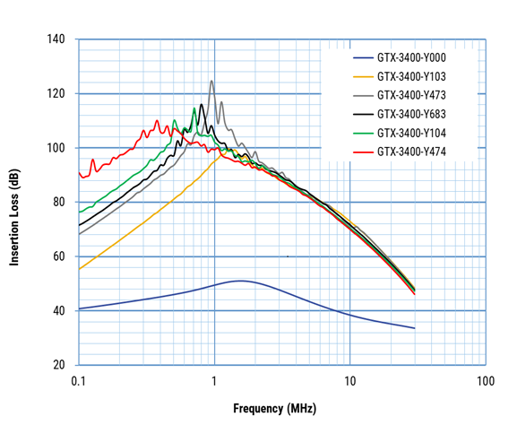
Figure 4– GTX three-phase attenuation characteristics for 6 different capacitor options
AC line filters are a requirement to attenuate common-mode and differential-mode noise. Although simple in principle, they are not easy to design and often require the input of an expert. Moreover, in three-phase power applications, the design complexity increases dramatically. Often, adequate filtering performance results in a large physical volume.
Nanocrystalline core technology alleviates the size constraints imposed by the choke components Combining three-phase integration and nanocrystalline technology, KEMET’s GTX three-phase family provides the desired frequency response within a small size. This approach overcomes constraints that otherwise push designers toward a custom solution, thereby helping to simplify and accelerate their projects.