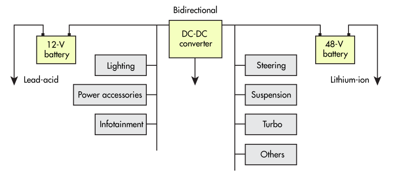
As shown in the figure below, modern automotive electrical systems often contain both 12 V and 48 V DC battery sources with a variety of DC-DC converters to supply the necessary subsystems. Voltage conversion in this domain is particularly challenging due to the rigorous automotive requirements for temperature, vibration, environment, and transient electrical conditions.

Overview of a 12/48-V automobile electrical system
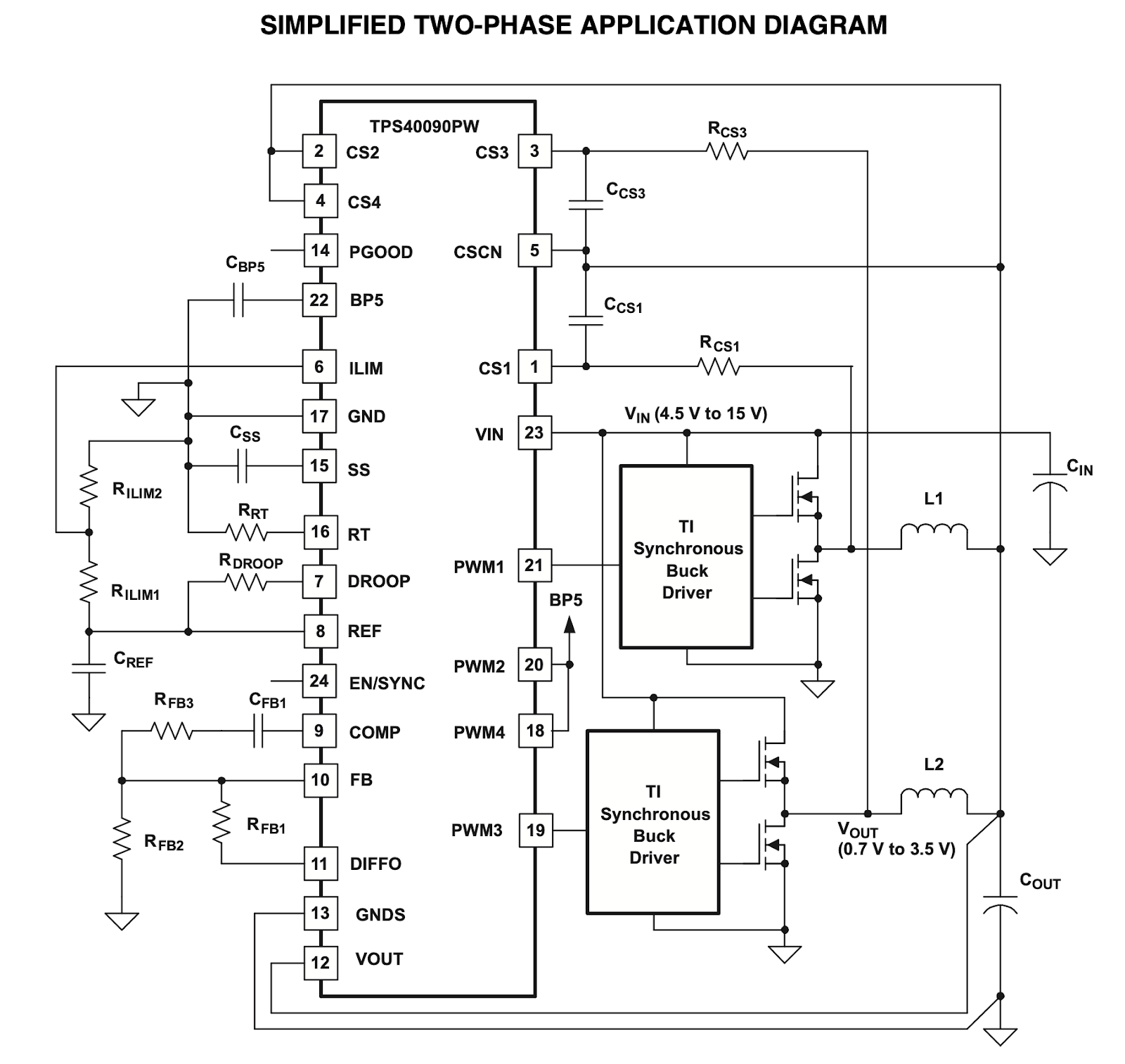
The Texas Instruments TPS40090-Q1 is one example of a DC-DC controller IC that is qualified for automotive applications per AEC-Q100 and is a good fit for high current voltage conversion from the 12 V battery system to a 3.3 V load. For the purposes of this example, assume the following requirements:
The focus in this example will be selecting the output capacitor considering ripple and ESR, while minimizing physical size.

TI’s TPS40090-Q1 High Frequency Multi-phase Controller (“TPS40090-Q1”)
The output ripple current due to the switching of the inductor can be calculated using the following equation:

Where Vout is the regulated output voltage; f is the switching frequency; L is the inductor value; and K is the phase factor
Since this particular chip supports up to four phases switching into the load simultaneously, the K factor reduces ripple and is approximately 0.57 based on a minimum duty cycle of 11%. The ripple current is therefore 7.46 A for a 0.6 µH inductor.
In order to determine the output capacitor value based purely on ripple current, the following equation can be used:

Where Vripple is the acceptable voltage ripple given by the output specification.
Using the calculated ripple from above along with the specified 50 mv voltage ripple, the required output capacitance is 355 µF.
In addition to pure capacitance, the parasitic series resistance must be accounted for. Using the following equation, a maximum ESR value can be determined:

Using the values above, the required ESR for the output capacitor must be at most 6.7 mΩ.
Thus far, only switching transients have been considered with respect to ripple. One should also estimate the output capacitance requirement for a worst case load transient. For example, during a transition from full load to no load, the output capacitor can be used to reduce voltage overshoot. This can be approximated by equating the inductor and capacitor energies to yield the following equation:

Where Vmax is the maximum allowable output voltage; Vnom is the nominal output voltage; L is the equivalent inductance (divide by 4 for a 4 phase design); and Ih is the peak output current.
For a Vmax of 105%, the required output capacitance is therefore 1,344 µF.
From these calculations, it can be seen that the ESR and the overshoot voltage drive the capacitor selection in the design. Using KEMET’s latest ultra-high CV capacitor series table, one can easily find electrolytic capacitors in the thousands of microfarads with ESR’s around 10-20 mΩ. So, for example, one might choose the PEH227KMP4420QE4 which offers:
4,200 µF of bulk capacitance
14 mΩ ESR @ 100 kHz and 20 ℃
9 A rated ripple current @ 125 ℃
20x35mm case size
32 VDC rating at 150 ℃
Placing two of these devices in parallel would satisfy the ESR and ripple current requirements while providing more than 6X the required bulk capacitance in a relatively small form factor. Most importantly, they offer automotive qualification for temperature, vibration, and lifetime reliability.
In many applications, including DC-DC voltage regulation, large bulk capacitors are required with low ESR and high ripple current capabilities. Aluminum electrolytics can be an excellent solution, especially when used in tandem with smaller ceramic capacitors. KEMET provides industry-leading capacitance per volume density performance along with excellent ripple and ESR characteristics. When combined with their advanced construction design for both axial and radial crown form factors, and their high tolerance to temperature and vibration, a solution emerges for even the most demanding automotive applications.