The development of the electrolytic capacitor (e-cap) has been one of the main factors in the successful miniaturization and increased performance of many modern-day electronics. The basic e-cap construction is shown in the figure below:
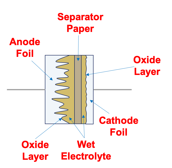
Figure 1 – Typical wet electrolytic capacitor (Courtesy of KEMET)
Since capacitance is a function of surface area, aluminum foils are first etched to create a rough contour with maximal contact area. Capacitance is also an inverse function of dielectric thickness. An oxide layer is grown on the anode foil surface to realize the thinnest possible dielectric for given voltage, while still following the aluminum contours.
Oxides act as a unidirectional dielectric, only blocking the flow of current in one direction. This leads to the well-known polarization of e-caps, as a reverse voltage will actively remove the oxide layer. Because the anode is roughly contoured, it is difficult to make electrical contact with the oxide layer for the capacitor’s second plate.
This is where the electrolyte comes into play. Traditionally, a “wet” liquid fills in the anode-oxide surface’s peaks and valleys and effectively creates the cathode. A second foil layer and a paper separator are added to fully complete the capacitor structure, producing an excellent terminal contact with this electrolyte. This aluminum-electrolyte-paper sandwich is then rolled or “wound” into a can and sealed with two terminals to realize a through-hole or surface mount (SMD) device.
The driving trend in e-cap technology is miniaturization while maintaining low series resistance (ESR) and high reliability. When considering the interface between the foil and the oxide layer, the electrolyte’s conductivity is the leading player in determining the ESR, often modeled as Rs shown below.
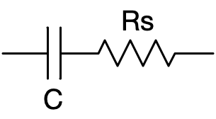
Figure 2 – Series resistance equivalent circuit (ESR)
ESR is such a critical parameter because it directly affects the peak ripple capability of the capacitor, along with its heat generation and temperature performance. The only real option to reduce ESR is to use an electrolyte with higher conductivity. Indeed, the early “wet” electrolytes were quickly replaced with “dry” solid electrolytes such as manganese dioxide and exotic organic conductors. These electrolytes improved conductivity by several orders of magnitude.
The discovery of highly conductive polymers in 1975 was one of the seminal events leading to extremely low ESR. These polymers yielded several orders of magnitude higher conductivity, as shown in the figure below:
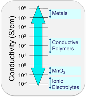
Figure 3 – Relative conductivities of different electrolytes
Much like their wet electrolyte predecessors, the poly(3,4-ethylenedioxythiophene) polymer conductor (PEDOT) is formed to fill the contours of the foil-oxide layer as shown below. The paper separator and cathode foil structure are preserved and modified with the polymer.
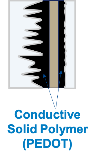
Figure 4 – Solid polymer capacitor construction
The latest innovation — hybrid e-caps — take polymer technology a step further by combining it with a wet electrolyte in the same device. The polymer serves to boost conductivity and reduce ESR, while the wet electrolyte maximizes contact surface area and increases voltage tolerance. A complete construction diagram of a hybrid aluminum polymer e-cap is shown below, including the rubber electrolyte seal and SMD lead frame.
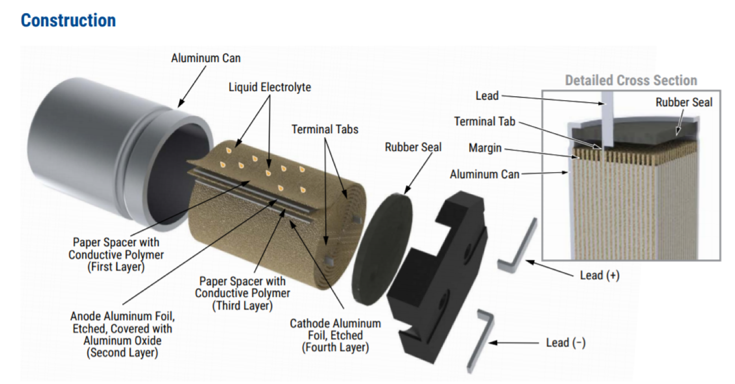
Figure 5 – Aluminum hybrid polymer capacitor construction
The combination of advanced materials and hybrid construction in these types of capacitors yields several game-changing benefits: high capacitance and voltage tolerance in a small package; extremely low ESR; high reliability through self-healing mechanisms; and an extensive environmental operating range.
Hybrid aluminum e-caps perform at the top of every category and exceptionally well in temperature and leakage tests. This performance can be attributed in large part to the low ESR provided by the hybrid electrolyte. The following figure demonstrates the exceptionally low ESR for hybrids compared to traditional electrolytes across the entire frequency range.
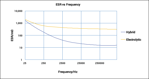
Figure 6 – ESR performance comparison of hybrid and traditional e-caps
When these capacitors are pushed to their limits of ripple absorption, the low ESR of the hybrid design has a marked improvement in heat generation. As shown in the following figure, transient simulations of high ripple currents resulted in a nearly 20°C temperature reduction of the hybrid designs.
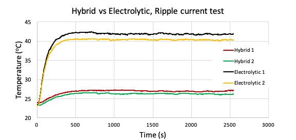
Figure 7 – Ripple current temperature comparison of hybrid and traditional e-caps
This type of temperature performance under high ripple conditions makes hybrid aluminum e-caps ideal for applications where sensitive downstream electronics require properly smoothed and decoupled power supplies in harsh environments. Automotive engine control units and electric vehicle inverters are two such examples.
In addition to temperature performance, automotive applications also require high reliability to meet AEC-Q200 standards. A common failure mode in electrolytics is a short or hole in the insulating oxide layer. Hybrid electrolytes enable two self-healing mechanisms to recover from this: the polymer’s local joule heating creates a non-conductive layer around the hole, and liquid electrolyte current flow reforms oxide on the foil surface. The second mechanism dominates in overall self-healing that allows smooth recovery of dielectric defects and enhanced reliability for the hybrid capacitor.
When all of these robust mechanisms are combined with anti-vibration mounting structures, automotive qualification is easily met with rated lifetimes exceeding 3,000 hours, shock tolerance of 30g, and operating temperature ranges from -55°C to 125°C. It is also worth noting that even though hybrid capacitors are more expensive than their traditional counterparts, their robust performance allows for much tighter rating margins and can result in price-competitive designs operating reliably at 90% of their rating.
KEMET is pleased to launch its first products in the aluminum hybrid e-cap space, capitalizing on the outstanding potential discussed in this article. These capacitors will be part of the A780 series and will initially include two values (56 µF and 100 µF) rated at 63 VDC.