This application guide refers specifically to aluminum electrolytic capacitors with a rectangular aluminum case utilizing a liquid electrolyte type construction. This application guide provides relevant technical information and some main advantages in choosing this capacitor’s technology type related to the usage of our AAR rectangular product family, as when used by a single cell or assembled as in a capacitor’s bank.
Typical applications for our AAR70 and AAR80 product families, which are AEC-Q200 qualified, include E-Mobility, such as on-board chargers (OBC), inverters, or wall boxes.
Due to its rectangular shape, our AAR product families offer the ability to stack capacitors to achieve a modular arrangement of the capacitors. The following are some of KEMET’s recommendations.
Mounting to a Printed Circuit Board (PCB) can be configured in different ways. The capacitor is designed for mounting with- or without- cooling by heat-sink. With the capacitor mounted to a metallic chassis (heat-sinked capacitor body), the ripple current capability is significantly improved. Mounting with heat-conductive adhesive or paste, will improve the cooling condition.
Depending on the load-profile and cooling condition, efficient cooling can increase the operational life by a factor of 2-6. For precise assessment, it is recommended to work directly with KEMET engineers using application information with specific calculations.
AAR80 and AAR70 capacitors are capable of up to 20g and 40g SIN-vibration, respectively. Optimal vibration resistance is achieved when the capacitor is stiff mounted to the PCB and/ or to the metallic chassis. This is achieved by gluing the capacitor to the PCB or to the chassis. Using heat-conductive adhesive ensures efficient capacitor heat dissipation. Note that the specified vibration resistance refers to the capacitor body vibration. The capacitor must be clamped by the body (stiff mounted) to fulfill the vibration specification.
A not stiff mounted PCB can act as a membrane. At the resonance frequency, the vibration can reach up to an order of magnitude higher acceleration, compared with the input vibration-load, to the application. To avoid significant resonance peaks, the PCB needs to have a short distance between the fixation points.
If the capacitor body has the potential to move during vibration (in relation to the PCB), this can easily result in breaking the wire terminals by fatigue. A stiff mounted capacitor to the PCB is crucial.
The capacitor can be mounted in any horizontal position ( Figure 1) or in an upright position (Figure 2 - A).
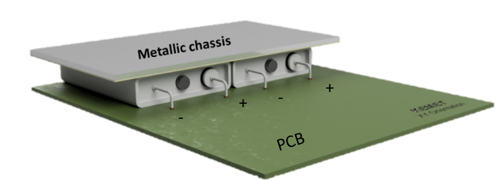
Figure 1 - A

Figure 1 - B
Figure 1– (A) Horizontal mounting position with 1-side heat-sinked. (B) Horizontal mounting position with 2-sides heat-sinked. Bends of the leads are representative.
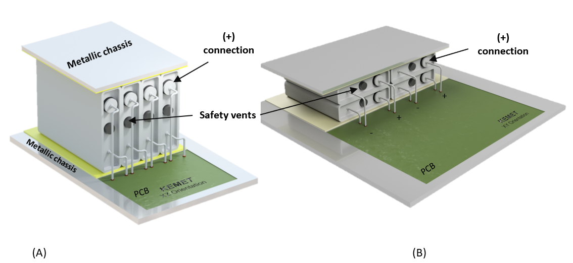
Figure 2 - (A) Upright position with 2-side heat sinked in a bank assembly. (B) Horizontal mounting position with 2-side heat sinked and stacking bank assembly. Bends of the leads are representative.
It's possible to stack the capacitors (Figure 2- B) to achieve a low height profile or to place them in an upright position bank (Figure 2 - A) to reduce the PCB footprint. Banks of capacitors mounted together will benefit from an adhesive applied to them, creating a rigid structure. Using a heat-conducting adhesive will result in a more evenly distributed temperature and improve heat-dissipation.
The adhesive should not cover the safety vent or rubber gasket (@ anode (+) termination), which prevents the internal generated gas from escaping during an overstress or catastrophic failure.
The capacitor should not be mounted upside down, (safety vent facing down) (Figure 3 - A). However, if the PCB is mounted in the vertical direction on the application, this position can be allowed (capacitor in a horizontal position see Figure 3 - B).
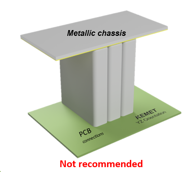
Figure 3 - A
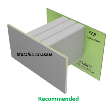
Figure 3 - B
Figure 3 - (A) Upside down position not recommended. (B) PCB placed vertically allowing capacitor mounting in horizontal position - recommended.
Insulation for a single capacitor or in between capacitors when mounting in a bank disposition is available up on request. For other mounting options, KEMET will discuss customized solutions with customers.
Footprint efficiency can be maximized with the use of a rectangular shape, thus empty space in between capacitors can be eliminated. In some cases, this can represent a reduction of 35% on the total footprint of the capacitor bank.
Below is a comparison of a bank of four capacitors connected in parallel for the same maximum rated temperature and capacitance/voltage: 85ºC max. rated temperature with 300µF and 450V.

Table 1 - Comparison of Rectangular AAR70A301JJ450 vs. Snap-In ALA7DA301CC450 considering total footprint occupied (Snap-in including empty space).
Rectangular AAR70A301JJ450 vs. Snap-In ALA7DA301CC450
The flat surface area of the AAR70 and AAR80 capacitor case allows for easy use with a heat-sink. As highlighted, with the capacitor mounted to the metallic chassis (heat-sinked capacitor body as Figure 1 - A with thermal paste mounting), the ripple current capability can be significantly improved due to low thermal resistance.
Heat-sink and ripple current optimization example:
AAR80 Ripple Current, Catalog Specification (@ Natural Conv. 105°C):
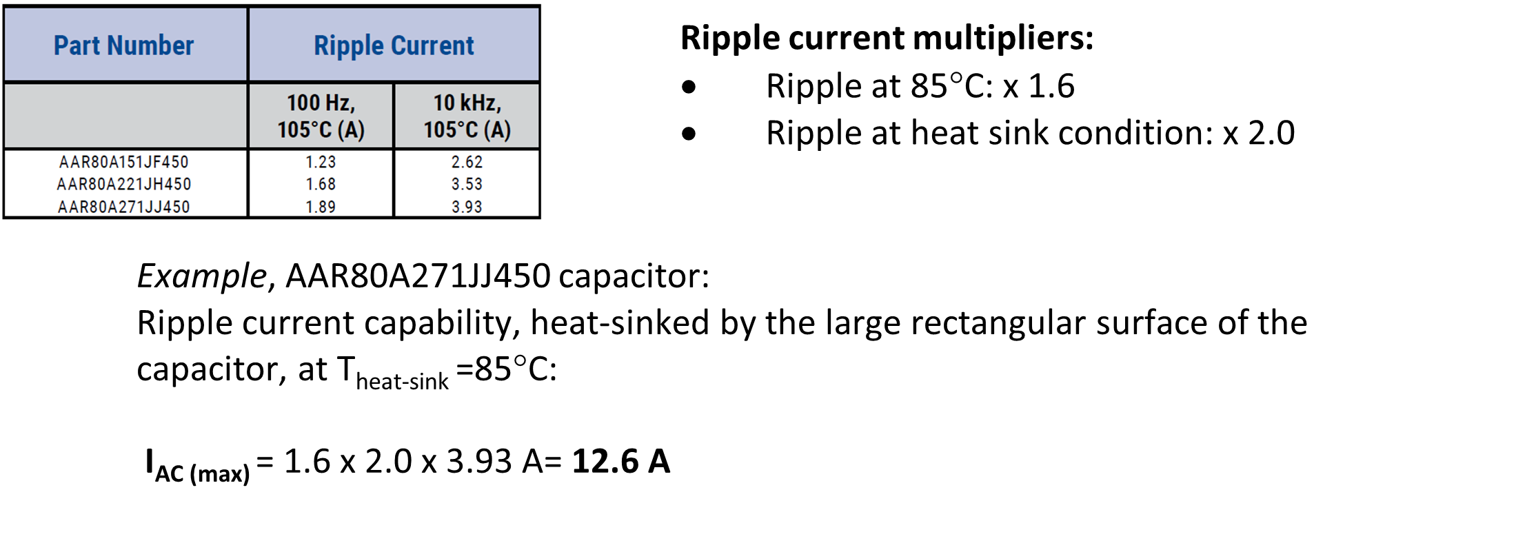
AAR80A271JJ450 is capable of 12.6 A ripple current, heat-sinked by the large surface of the capacitor, at 85°C.
Note, using multiple capacitors stacked together or in a bank configuration, can change the thermal dynamics, and therefore the ripple current capability compared to a single capacitor. Contact KEMET for assistance in this case.
Cleaning of aluminum electrolytic capacitors is susceptible to damage by certain cleaning solvents. Cleaning solvents containing halogenated hydrocarbons, especially chlorinated ones, are generally not recommended. These solvents can diffuse through the rubbers into the capacitor and are then converted electro-chemically to free chlorides, which can cause corrosion. This diffusion can result in a pressure build-up that can destroy the capacitor.
Cleaning solvents that can be used without precautions:
Halogenated Hydrocarbons contain CFCs and as such, are ozone-depleting chemicals (ODCs). It is not recommended to be used as cleaning solvents. In addition, these solvents can be damaging to electrolytic capacitors through absorption into the rubbers followed by subsequent diffusion into the case, and can attack the winding, leading to premature failure.
Overall, the main benefits of using AAR70 and AAR80 product families are:
Please contact a KEMET sales representative for more information on the AAR Rectangular product families.