When applications require extremely high ripple current, heat-sink solutions can be used to preserve A780 operational life.
KEMET’s Electrolytic Innovation Center (EIC) analyzed the performance of A780 capacitors with heat-sinked terminals, forecasting the behavior on possible applications of our customers. EIC suggestion is to apply a heat-sink in contact with the PCB with the mounted electronic devices, as follows:
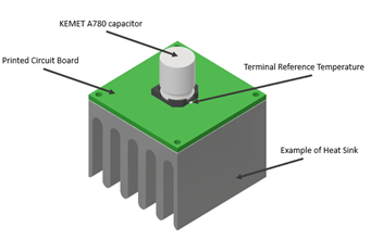
Figure 1 - KEMET A780 mounting example
In the absence of forced air cooling, heat dissipation control can be improved by applying a metallic heat-sink/radiator on the backside of the PCB. Using the metallic heat-sink/ radiator on the backside of the PCB can allow for effective cooling of the system and consequently higher ripple capability. The thermal resistance of the PCB between capacitor terminals and the heat sink should be considered for thermal modeling to specific applications by the customers.
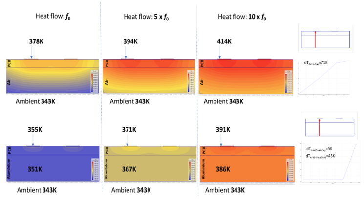
Figure 2 - PCB thermal profiles in Air without convection and with Aluminum Heat-Sink plate without forced cooling. (PCB thickness 1.6mm; Top metallization thickness 100um; Top metallization width corresponds to the terminal positions of D10xL12 V-chip capacitor; Heat-sink thickness 5mm)
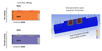
Figure 3 - PCB thermal profiles with Aluminum Heat-Sink plate with forced cooling (PCB thickness 1.6mm; Top metallization thickness 100um; Top metallization width corresponds to the terminal positions of D10xL12 V-chip capacitor; Heat-sink thickness 5mm)
The thermal resistance of PCB is one of the main contributors to the total thermal resistance of the heat dissipation pathway. The thermal resistance of multilayer PCBs can be significantly lower than single-layer PCBs of the same thickness. Thus, applications with a low thermal resistance multilayer PCB can be capable of higher ripple currents. In other words, a higher current can be applied at the same heat-sink temperature, or a lower terminal temperature can be ensured at the same ripple current.
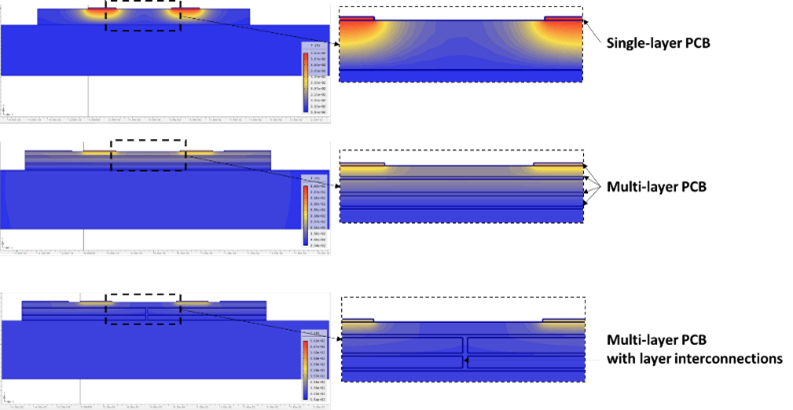
Figure 4 - Multilayer PCB thermal profiles with Aluminum Heat-Sink plate with forced cooling (PCB thickness 1.6mm; Top metallization thickness 100um; Top metallization width corresponds to the terminal positions of D10xL12 V-chip capacitor; Heat-sink thickness 5mm)
During Ripple Current capability experiments, one side of a single-layer PCB was assembled with a total thickness of 1.6mm and 100µm on the top metalized path thickness. A standard aluminum heat radiator was attached to the other side of the PCB to ensure a constant temperature on the capacitor terminals. Thermal paste was used to minimize the interface thermal resistance.
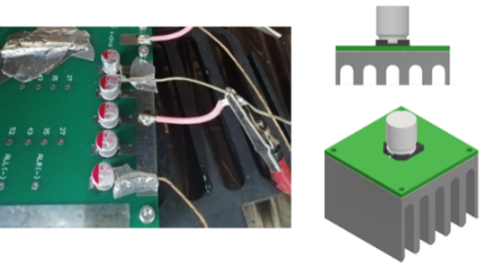
Figure 5 - Ripple Current capability validation set-up details
Please see more detailed information about the set-up in the Appendix.
The terminal temperature was used as a reference point to fix conditions and calculate Ripple Current capability for different lifetime values, as shown in figure 6.
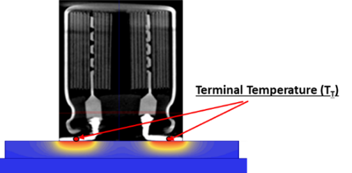
Figure 6 - Terminal Temperature (TT) is used as a reference in case of heat sink usage
Lifetime at specified ripple current values are ensured if terminal temperature TT is not exceeded.
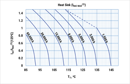
Figure 7 - Operational life, when using a low thermal resistance path, at terminal temperature TT and ripple current IAC applied
IRAC(2) corresponds to the maximum Ripple Current specified for each case and should be consulted in Table 1 of KEMET’s A780 series datasheet. The dashed lines correspond to the maximum ripple current allowed for each case. For example, 135°C on the terminal does not allow for applying the Ripple Current for more than what corresponds to IAC/IRAC(2)=1.2.
Ripple current capability of A780 series capacitors can be significantly increased if mounted on a heat‑sink PCB. Higher ripple current can be reached for the heat‑sink PCB vs. regular mounting for the same hot spot temperature due to better heat dissipation through the low thermal resistance path (terminal to heat-sink). Thus, operational lifetime is equal for both conditions since it is a function of hot spot temperature. For example, 63V 100µF D10 x L12.2 V‑chip hybrid capacitor (A780MS107M1JLAS030) is rated for 4,000 hours of operational life at ambient temperature of 125oC and ripple current of 1.8 ARMS for a regular PCB mounting. The heat‑sink PCB is rated 2.6 ARMS ripple current for the same lifetime and terminal temperature.
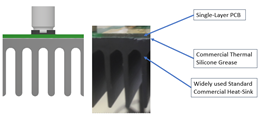
Heat sink specifications
| Characteristic | Value |
|---|---|
| Dimensions (See detailed dimensions below) | 200 x 200 x 25 mm |
| Thermal Resistance | 0.5 K/W |
| Material | Aluminum |
| Color | Black |

Thermal paste specifications
| Characteristic | Value |
|---|---|
| Thermal Conductivity | 2.7 W/M.K |
| Specific Gravity | 205 g/cm3 |
| Color | Grey |
| Application Temperature | -30ºC to +300ºC |
| Dielectric Constant | 5.1 |